convert voltage of stax SRM-300 from japanese 100V to NA 110V
May 27, 2008 at 7:34 PM Thread Starter Post #1 of 13

Spare Tire

100+ Head-Fier
Joined
May 12, 2006
Posts
234
Likes
12
Hi, I know there exist a thread here in head-fi with instructions on how to do this, but i can't find it anymore. I haven't been on these boards for a long time (happy wallet) so it's hard for me to track it down (was it in that long stax thread?)
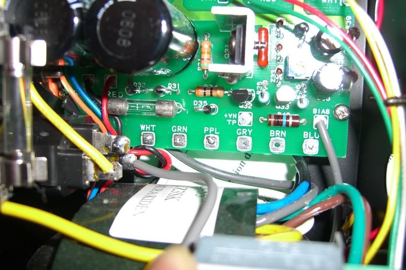
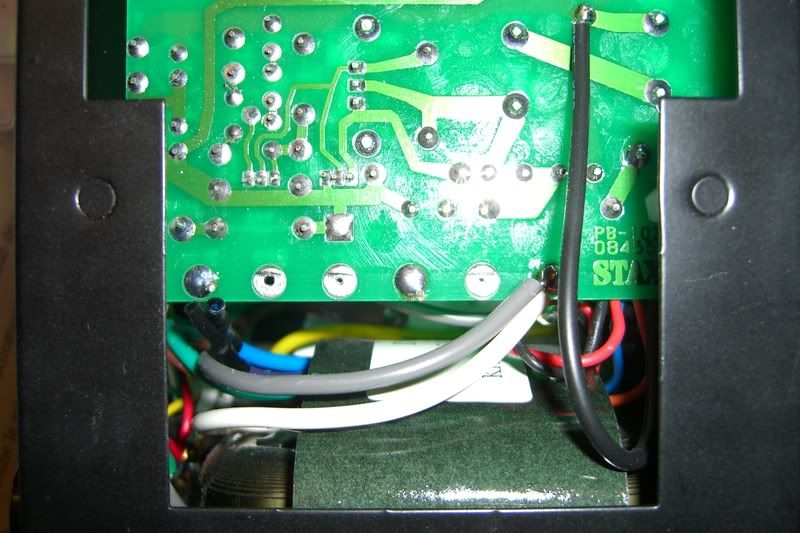
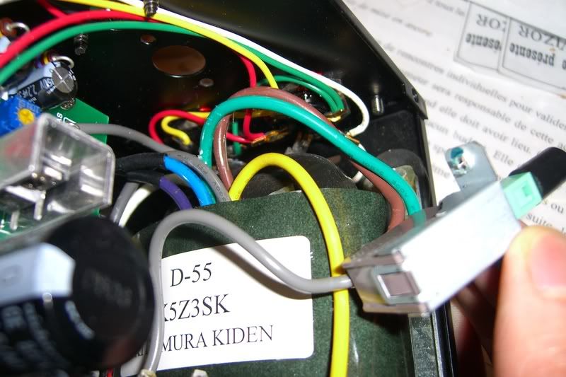
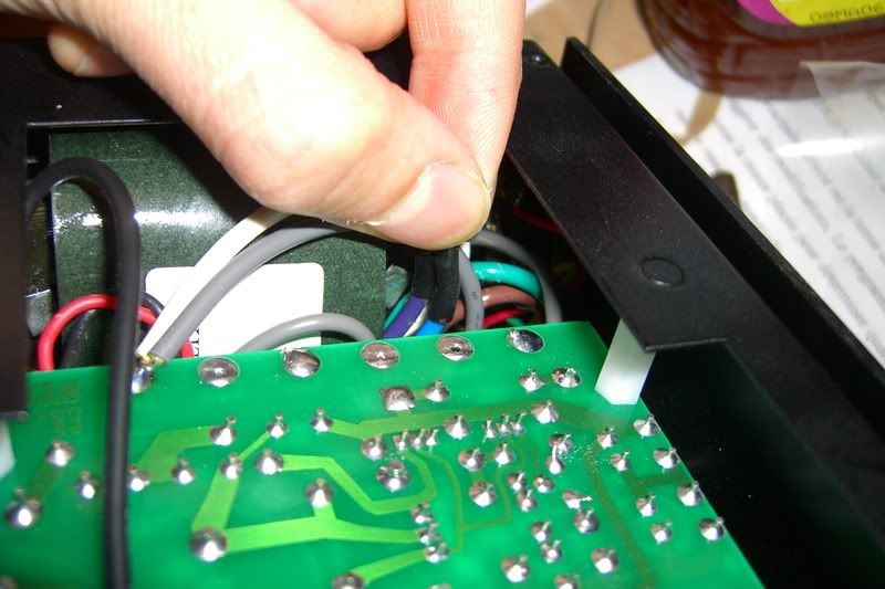
I bought a Stax SRM-300 from audiocubes and it's on japanese voltage. They included a converter and that served well for a few years. But now i have the torx screwdrivers, spare time and am ready to take the thing appart and rewire it to NA voltage. Could someone repost the pictures and tutorial to do this? Thanks.
 
May 27, 2008 at 8:20 PM Post #2 of 13
This could be easy or very hard to pull off, depending on how your amp was built. There was no tutorial for doing this and the only thing you need is the correct order of connections which range from 1-6. How those connections are made inside the amp is the problem as Stax has a tendency to make it rather hard to convert the amps which includes damaging the transformers by cutting some of the leads.
 
May 27, 2008 at 11:51 PM Post #3 of 13
Well, from what i can remember, there was a picture of the innards of the SRM-300 with leads having colored sleevings and someone had actually tried it. I think doctor Kevin Gilmore said which lead had to go where but i can't seem to find the thread. A multi paged thread at that.
 
May 28, 2008 at 3:41 PM Post #4 of 13
Quote:

Originally Posted by Spare Tire /img/forum/go_quote.gif
Well, from what i can remember, there was a picture of the innards of the SRM-300 with leads having colored sleevings and someone had actually tried it. I think doctor Kevin Gilmore said which lead had to go where but i can't seem to find the thread. A multi paged thread at that.


The SRM-300 uses a different transformer design then the rest of the Stax range so it's impossible to tell without detailed internal pics as I've never owned one of these. A normal Stax amp has 6-7 wires on the primary which need to connected together in the right order.
 
May 28, 2008 at 8:56 PM Post #8 of 13
a poor picture of that was posted some time ago. Uses a R core
transformer. Likely the wires to the 120 vac windings are cut
close to the transformer, so modifications may require skill with
a razor knife to get at the wires.

picture would speak loudly as to whether or not this is possible.
 
May 28, 2008 at 11:17 PM Post #9 of 13
Hum. I'll try to take some pics but i don't have a digital camera. I'll see if any friends can lend me theirs to take some shots. I'll see what i can do, it'll be reference for the community too if that happens.

As for the link, yeah i think that's the thread. Indeed it's the 313, not the same thing. But the pictures are gone anyways.
 
May 30, 2008 at 3:08 PM Post #10 of 13
Here are the pictures as promised.
SRM300_powersupply_01.jpg

SRM300_powersupply_02.jpg

SRM300_powersupply_03.jpg

SRM300_powersupply_04.jpg

Looks a lot different than the SRM-313. Simpler if you ask me, but i don't know what they mean, so i hope i shot the right place.
Grey, green and brown leads are connected to the power switch. Grey and white are connected to the back of WHT.
The blue and purple leads are quite short. But would there be any problems if i extend them with another piece of wire? I mean, it's just a powersupply, would it affect my sound in any way to have a cheap piece of wire and some extra solder joints? Or i could probably just solder them to the front of the plate instead of the back, that would be easier.
 
May 30, 2008 at 3:22 PM Post #11 of 13
You want to remove the brown and green wires from the power
switch and insulate them, or solder them back to places on
the circuit board. Then you want to take the heat-shrink off
of the blue and purple wires, solder them together and wire to
the power switch. Then you will have a 120vac unit.
 
May 30, 2008 at 3:33 PM Post #12 of 13
So if i understand well:
brown -> BRN
green -> GRN
Which means brown and green are connected to nothing, like blue and purple was?

And:
blue + purple -> power switch

Wow, that was easier than i though.
 
Aug 15, 2010 at 9:50 PM Post #13 of 13
Holy necrorevive batman. Here are just a two more pics of what it looks like after the operation, for reference.
They cut off the lead very short at the factory and it was quite a tight fit trying to solder blue & purple to the switch. Your amp might be less lucky.


Here is the switch screwed back on. Not much play left for the wires.


Users who are viewing this thread

Back
Top