dhaninugraha
100+ Head-Fier
- Joined
- Nov 19, 2008
- Posts
- 190
- Likes
- 6
hi guys

having built 5 CMoy amps with good success (first 2 amps followed Tangentsoft's schematic, last 3 amps followed Chu Moy's), I've been wondering what improvements I can make to the CMoy, besides using better parts and buffering the virtual ground. balanced CMoy came to my mind a few times, but I had difficulties looking for resources to study about it, so I kinda scrapped the idea (they'll be some sort of "far in the future" project).
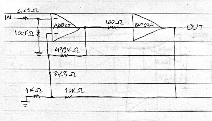
anyways. when I was skimming through the PPA pages at Tangentsoft, I noticed that Tangent mentioned "Jung multiloop" there. and the multiloop happened to appear at the PINT page too. I was wondering, what the hell is this multiloop stuff? so I looked at Walt Jung's explanation as well as looking at the PPA schematic showing the multiloop (honestly I couldn't really understand the stuff at Jung's page -- they're too technical for my critter brain), I came to understand that the Jung multiloop involves two loops: local loop and global loop. and as I examine the PPA schematics further, I also note the presence of a buffer there. a thought came to my mind: why not incorporate the Jung multiloop and buffer into my CMoy?
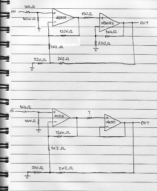
so this is the schematic I drew yesterday (the bottom schematic is an alternative to the top):
my questions are:
1) would the 551/552 be good at buffer job?
2) I read the 551/552 datasheet and it says that 551 is good for unity gain, so is it okay for me to connect the 551's output straight to the inverting input? and is it also okay to make the 552 buffer have a gain of 6, as AFAIK the 552 is stable at gains above 5?
3) I wanted the AD825's local loop to have a gain of 100 and the global loop to have a gain of 11 (hence the resistor values), are these values good?
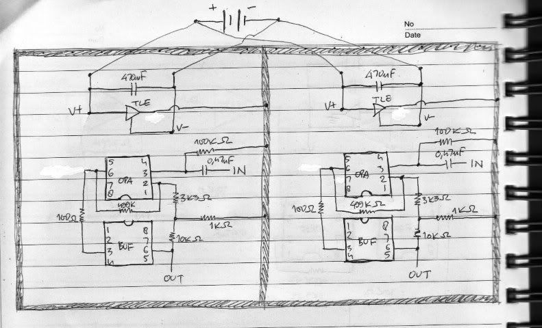
4) I'm planning to bypass the AD825's power rails with 0.1uF Wima MKS2 in parallel w/ 0.01uF C0G ceramic. is this good? do I need to bypass the buffers' power rails as well?
5) on the bottom schematic, I put a question mark on the resistor symbol between the AD825's output and OPA551's input. do I need this resistor or do I not, and if I do, what is the best value to put in there? because I got the notion that both inputs must see similar resistance, am I right?
6) any alternative(s) besides the 551/552? IIRC, majkel said that the AD8397 is better than 2x BUF634 at this job... however it was also mentioned that the 8397 is somewhat cranky due to its bipolar input... what modifications do I need to do to my schematic to accomodate the 8397?
any inputs would be very very much appreciated
and big apologies for my bad English and bad drawing

having built 5 CMoy amps with good success (first 2 amps followed Tangentsoft's schematic, last 3 amps followed Chu Moy's), I've been wondering what improvements I can make to the CMoy, besides using better parts and buffering the virtual ground. balanced CMoy came to my mind a few times, but I had difficulties looking for resources to study about it, so I kinda scrapped the idea (they'll be some sort of "far in the future" project).
anyways. when I was skimming through the PPA pages at Tangentsoft, I noticed that Tangent mentioned "Jung multiloop" there. and the multiloop happened to appear at the PINT page too. I was wondering, what the hell is this multiloop stuff? so I looked at Walt Jung's explanation as well as looking at the PPA schematic showing the multiloop (honestly I couldn't really understand the stuff at Jung's page -- they're too technical for my critter brain), I came to understand that the Jung multiloop involves two loops: local loop and global loop. and as I examine the PPA schematics further, I also note the presence of a buffer there. a thought came to my mind: why not incorporate the Jung multiloop and buffer into my CMoy?
so this is the schematic I drew yesterday (the bottom schematic is an alternative to the top):
my questions are:
1) would the 551/552 be good at buffer job?
2) I read the 551/552 datasheet and it says that 551 is good for unity gain, so is it okay for me to connect the 551's output straight to the inverting input? and is it also okay to make the 552 buffer have a gain of 6, as AFAIK the 552 is stable at gains above 5?
3) I wanted the AD825's local loop to have a gain of 100 and the global loop to have a gain of 11 (hence the resistor values), are these values good?
4) I'm planning to bypass the AD825's power rails with 0.1uF Wima MKS2 in parallel w/ 0.01uF C0G ceramic. is this good? do I need to bypass the buffers' power rails as well?
5) on the bottom schematic, I put a question mark on the resistor symbol between the AD825's output and OPA551's input. do I need this resistor or do I not, and if I do, what is the best value to put in there? because I got the notion that both inputs must see similar resistance, am I right?
6) any alternative(s) besides the 551/552? IIRC, majkel said that the AD8397 is better than 2x BUF634 at this job... however it was also mentioned that the 8397 is somewhat cranky due to its bipolar input... what modifications do I need to do to my schematic to accomodate the 8397?
any inputs would be very very much appreciated
and big apologies for my bad English and bad drawing