CMoy op-amp rail caps question...
Jul 2, 2011 at 1:01 AM Thread Starter Post #1 of 6

Lavalier

New Head-Fier
Joined
Jul 2, 2011
Posts
7
Likes
0
Hello everyone! (first post here)
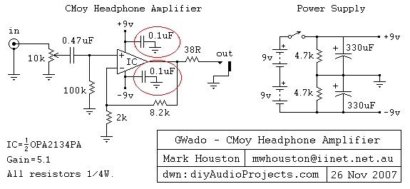
I recently completed my first CMoy headphone amp and came across this schematic...


I noticed the circled 0.1uF caps in the op amp rails and wanted to know the reason these were added.
Since there's already 330uF caps going to virtual ground, what's the logic in adding another 0.1uF to each rail?
 
Jul 2, 2011 at 1:49 PM Post #3 of 6
 
Thanks Groundloop! I found this article that does a good job explaining the purpose of bypass capacitors. 
 
http://www.seattlerobotics.org/encoder/jun97/basics.html
 
So from what understand, the larger 330uF capacitors are more efficient at smoothing out larger/slower variances in voltage/current (lower frequency AC signals) while the .1uF caps can react much quicker to unwanted higher frequency changes (ripple) in the rail supply. 
 
I'm curious though, how much (or little) of an audible difference adding or omitting these bypass caps in a Cmoy circuit will have..
 
Jul 2, 2011 at 4:01 PM Post #5 of 6
Interesting. So, in my case, I'm using the recommended (Tangent) OPA2132PA op-amp. I assume since he did not specify them in the circuit that this one of the "basically no change" op amps... It already sounds great as is, so my guess is that they would have negligible sound differences.
 

Users who are viewing this thread

Back
Top