Cmoy Connection Help

Feb 7, 2005 at 12:17 AM Thread Starter Post #1 of 17

dmunky

100+ Head-Fier
Joined
Feb 1, 2004
Posts
117
Likes
1
Hi, I'm on the verge of completing a Cmoy amp. The only thing is, tangentsoft's instructions just leave you hanging without telling you how to hook up the wires to the volume knob and audio jacks. And how about grounding?

These are the last things I have to connect:
1 Volume control, Panasonic 10K, horizontal mount (EVJ-C20) with 6 prongs
2 Stereo mini jacks (3.5mm) from digikey part #CP-3535 with 5 prongs

Which of these prongs are actually used and how would I go about grounding them? I'm using an Altoid's mint tin and a 276-0150 board from Radio Shack.

I have already done a search and wouldn't have posted this if I found anything useful. Please help with pics or schematics. Thanks
 
Feb 7, 2005 at 1:14 AM Post #3 of 17
Thanks for the quick reply. I already read that in my search for an answer, but it still doesn't really help explaining which things are wired where. In the guide, it describes an I/O jack with 3 prongs, whereas this one has 5. Can anyone help?
confused.gif
 
Feb 7, 2005 at 1:38 AM Post #4 of 17
I understand what your asking for:

do a serach on this forum for panasonic pot wiring and it will pull up a post with the pin out for the volume pot.

Basically you need to connect 2 wires from a jack to the pot (this is your input)

Then connect two wires from the pot to the input caps on your amp

Then connect two wires from another jack to the left and right output of the amp (R5 on both sides) (this is the jack that the headphones go into)

Finally connect a wire to all of the ground spots on all jacks and the pot to the ground on the amp.

I would post a pdf of it that I made but I'm on vacation (Laughing)

Hope that helps
 
Feb 7, 2005 at 3:29 AM Post #7 of 17
Ok, the volume chart helps greatly, but still, there's nothing telling me where to connect the wires to which prongs on each audio jack (since there are 5).

I looked up charts on digikey and mouser, but I still can't find the right place to hook the wires up. I know people would say use an Ohm meter but that's something I don't have right now. Being the most common portably amp, there surely has to be other's who have run into the same problem. I followed tangensoft's guide perfectly up to that point with all the same parts he recommends from digikey.

I tried the configuration of closest prong with farthest prong but it doesn't work.

Any ideas? Or someone willing to post detailed pics? Thanks
 
Feb 7, 2005 at 3:48 AM Post #9 of 17
digi had a pic attached at the bottom of his post showing the wiring. Also, Digikey has the datasheet for that jack here, which will also give you the pinout. Remember that the tip of a stereo 3.5mm plug is the left channel, the ring is the right channel, and the sleeve is the ground. I only mention this because on some jacks you can see what is contacting what when you insert the plug. On CUIs datasheet drawing, pin 1 is ground, pin 2 is right and pin 5 is left.
 
Feb 7, 2005 at 3:54 AM Post #10 of 17
Wow actually the 'd' in dmunky stands for drunken! What a weird coincidence. I also happen to be making the cmoy in a curious george altoids tin. Currently I've put my tools away and am gonna take a step back from the project, relax, take a deep breathe, and come back to it tomorrow. Thanks so much for the quick and helpful replies people!
 
Feb 7, 2005 at 7:01 AM Post #12 of 17
Quote:

Originally Posted by dmunky
Ok, the volume chart helps greatly, but still, there's nothing telling me where to connect the wires to which prongs on each audio jack (since there are 5).


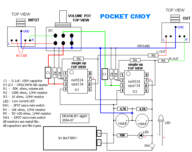
I have modify the drawing a moment ago,wish that is ok
cool.gif


cmoy-single-amp.gif


to Anthrax,
this pot is all right for cmoy.you can easily build a cmoy basis on the drawing.

good luck!
Zang
 
Feb 7, 2005 at 7:18 AM Post #13 of 17
just use your multimeter and a mini to mini cable to work out where you need to put the wires on the jacks, plug the cable in connect the multimeter to a pole on the other end then the other lead to the jack connections. use resistance mode to test which conducts....
 
Feb 8, 2005 at 1:41 AM Post #15 of 17
Quote:

Originally Posted by skyskraper
just use your multimeter and a mini to mini cable to work out where you need to put the wires on the jacks, plug the cable in connect the multimeter to a pole on the other end then the other lead to the jack connections. use resistance mode to test which conducts....


that's the best way to find out which to wire for input and output. many i/o jacks are configured differently, so you should just test it out.

the tip of the plug is the left channel, the middle "ring" is the right channel, and the bottom "sleeve" is the ground. so find out which pole is left and wire it to left, etc.
 

Users who are viewing this thread

Back
Top