Cmoy Buffered outputs using NJM 4556AD
Feb 17, 2014 at 10:02 PM Thread Starter Post #1 of 12

backspace119

Member of the Trade
Joined
Feb 3, 2014
Posts
67
Likes
10
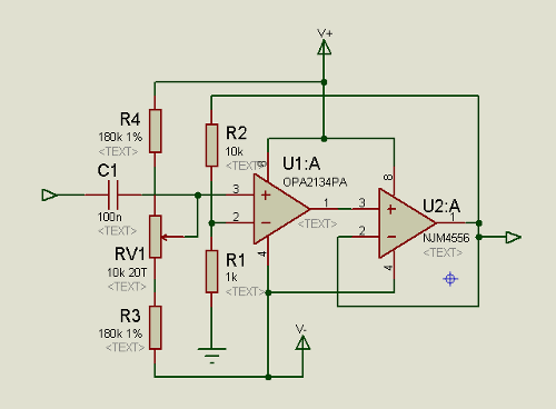
My opamps that I had ordered (OPA2134PA and NJM 4556AD) came recently and so I have been tampering with my CMoy again. I tried both and found that the 4556 worked much better for my purposes (low impedance headphones with a bass boost circuit implemented) the only issue was, with the bass boost all the way up, the DC offset was around 400 mV....definitely an issue...with the 2134 it wasn't an issue (offset with bass boost all the way up was 17 mV) but it couldn't handle as much current as the 4556 and thus distorted at levels that the 4556 wouldn't. I decided I would try to get the best of both and use the 4556 as a buffer. I built the circuit as per the usual CMoy except I shorted the output of the OPA to the + input of the 4556 and routed its output back to the OPAs - Input through a 2.2K resistor (gain value is ~5.7 (ground resistor is 470 and gain is 2.2k) I also shorted the 4556s output to its - input making it unity gain. I also do not use a vGnd as it could create more distortion issues. I use 2 batteries and a real ground.
 
When I turned it on i got an offset in both channels of about 6.9 Volts. The 9v batteries I'm using are a bit drained (measure at 7.98 Volts and 7.1 Volts) but I don't think that should cause this  bad of an offset. I checked for shorts and found none and used a meter to make sure there were no shorts and all that. I looked at some previous threads about this and it would seem this circuit should work. 
 
Whats the issue here? any ideas?
 
Is the 4556 not unity gain stable (checked the sheets but couldnt find anything about it being unity gain stable)
 
Sorry for no pics I don't have a camera :frowning2:
 
Also sorry for no schematic but I didn't have time to make one, I might try to make one tommorow to show my implementation. The main way it works is:
 
 
                          OPA => 0 ohms=>(+)4456 => 0 ohms=I
 gnd <= 100K <= (+)(-) <= 2.2K ohms <= (-)  <========I
                               I
                              V
                            470 ohms ====> gnd
 
 
Any help greatly appreciated and I thank you for your time in advance
 
 
EDIT: After fooling with the design it still has this issue. Here's a schematic. I am really quite lost at this point.


Please if anyone has any idea whats going wrong please help. It is spitting out 7-8V DC (seems to fluctuate some times)
 
Feb 18, 2014 at 11:50 AM Post #2 of 12
  My opamps that I had ordered (OPA2134PA and NJM 4556AD) came recently and so I have been tampering with my CMoy again. I tried both and found that the 4556 worked much better for my purposes (low impedance headphones with a bass boost circuit implemented) the only issue was, with the bass boost all the way up, the DC offset was around 400 mV....definitely an issue...with the 2134 it wasn't an issue (offset with bass boost all the way up was 17 mV) but it couldn't handle as much current as the 4556 and thus distorted at levels that the 4556 wouldn't. I decided I would try to get the best of both and use the 4556 as a buffer. I built the circuit as per the usual CMoy except I shorted the output of the OPA to the + input of the 4556 and routed its output back to the OPAs - Input through a 2.2K resistor (gain value is ~5.7 (ground resistor is 470 and gain is 2.2k) I also shorted the 4556s output to its - input making it unity gain. I also do not use a vGnd as it could create more distortion issues. I use 2 batteries and a real ground.
 
When I turned it on i got an offset in both channels of about 6.9 Volts. The 9v batteries I'm using are a bit drained (measure at 7.98 Volts and 7.1 Volts) but I don't think that should cause this  bad of an offset. I checked for shorts and found none and used a meter to make sure there were no shorts and all that. I looked at some previous threads about this and it would seem this circuit should work. 
 
Whats the issue here? any ideas?
 
Is the 4556 not unity gain stable (checked the sheets but couldnt find anything about it being unity gain stable)
 
Sorry for no pics I don't have a camera :frowning2:
 
Also sorry for no schematic but I didn't have time to make one, I might try to make one tommorow to show my implementation. The main way it works is:
 
 
                          OPA => 0 ohms=>(+)4456 => 0 ohms=I
 gnd <= 100K <= (+)(-) <= 2.2K ohms <= (-)  <========I
                               I
                              V
                            470 ohms ====> gnd
 
 
Any help greatly appreciated and I thank you for your time in advance

 
Its broken. 
 
Building a more complicated thing before you have gotten a less complicated thing working satisfactorily* is most unwise. 
 
I find it very hard to believe that you don't have a camera in a cell phone. Act like you are "texting" the photo, and type your email address in the "to" field. Set the quality to really big. Nobody wants to see 100x100pixel images. 
 
*In certain cases one may settle for learning why the less complicated thing failed in incredibly high detail. This mostly applies to situations where the more complicated design solves problems that were not understood or accounted for in the less complicated design but it is a very solid guideline for DIY. 
 
Feb 18, 2014 at 12:22 PM Post #3 of 12
   
Its broken. 
 
Building a more complicated thing before you have gotten a less complicated thing working satisfactorily* is most unwise. 
 
I find it very hard to believe that you don't have a camera in a cell phone. Act like you are "texting" the photo, and type your email address in the "to" field. Set the quality to really big. Nobody wants to see 100x100pixel images. 
 
*In certain cases one may settle for learning why the less complicated thing failed in incredibly high detail. This mostly applies to situations where the more complicated design solves problems that were not understood or accounted for in the less complicated design but it is a very solid guideline for DIY. 

bud. Im a programmer. I'm very technical. If I had a camera, I'd use it. I have a dumb-phone that unfortunately does not even take pictures (at least not ones that would mean anything to anyone. They are dark and distorted and you can barely make anything out, let alone circuits). I had it working before I built this as well.
 
EDIT: 
I apologize if I offend you with this but I hate being talked down to, especially when it comes to electronics.
 
Another edit:
If I had the money for a better phone I'd get one. But I don't. The way I pay for my parts is through a club at school that does things like this. When they have some extra cash, they let me buy parts for projects like this
 
Feb 18, 2014 at 5:50 PM Post #4 of 12
I apologize if I offend you with this but I hate being talked down to, especially when it comes to electronics.

Well..... did you know Old McDonald is a really bad speller?
 
The word is decelerate.
 
"Decelerate, d, e, c, e, l, e, r ,a, t, e, e, i, e, i, o."
 
Bzzzt.
 
Feb 18, 2014 at 8:56 PM Post #5 of 12
When you fix your misconnected cmoy, then you can compensate its output offset:- http://electronics.stackexchange.com/questions/34071/how-do-i-correct-offset-voltage-of-opamps-which-have-no-explicit-offset-null-pin.
 
w
 
Feb 18, 2014 at 10:31 PM Post #6 of 12
  When you fix your misconnected cmoy, then you can compensate its output offset:- http://electronics.stackexchange.com/questions/34071/how-do-i-correct-offset-voltage-of-opamps-which-have-no-explicit-offset-null-pin.
 
w

no matter what I changed values to it didn't seem to work. I even tried to add local feedback to both but I dont think it was working (tried a lot of configurations today not sure if it worked or not) finally got it working by seperating feedback loops (basically having both have their own local feedback) and the DC Offset makes me very happy now (1 mV left 2 mV right) I'm adding back my bass boost tommorow to see how much worse it gets but for now I'm happy. 
 
P.S. thanks for the link
 
Feb 18, 2014 at 10:41 PM Post #7 of 12
  When you fix your misconnected cmoy, then you can compensate its output offset:- http://electronics.stackexchange.com/questions/34071/how-do-i-correct-offset-voltage-of-opamps-which-have-no-explicit-offset-null-pin.
 
w

So after reading this article, I think I have a better understanding....so, if I have say, +50 mV of offset on a channel, I can take a high value pot, hook V- up to one end and ground to the other, and then the middle pin to the inverted input, between it and the input, put a 10 ohm resistor to ground.
 
After I do this I can adjust the pot until it is delivering -50 mV of voltage to the inverted input
 
would that solve the issue (this is for future refrence)
 
Feb 19, 2014 at 12:26 AM Post #8 of 12
It's not easy to visualize a circuit from these 'word pictures', and there's a lot of opportunity for misunderstanding. That's why we use schematics. Download a copy of LTSpice, it is based around a schematic capture package. Draw your circuit, then take a screenshot and post it. You'll get a lot more positive feedback if people aren't struggling to understand exactly what you're talking about. LTSpice is a (free) simulator anyway, it'll allow you to answer a lot of questions for yourself.

You have some basic misunderstandings about how opamp circuits work. Firstly, a negative voltage applied to the inverting input produces a positive output. That is to say, if you make the inverting input negative relative to the non-inverting input, you will get a positive swing at the output. The swing is multiplied by the voltage gain of the opamp. A gain of 1,000,000 is not uncommon.

When negative feedback is applied (the output is connected to the inverting input), the opamp tries to force the DC voltage at the inverting input to be identical to the voltage at the non-inverting input. This means that the DC output will be at the same voltage as the non-inverting input.

The normal effect of connecting a negative feedback loop is to constrain the overall (closed-loop) gain to a value considerably less than the opamp's native gain. The actual gain then becomes the ratio between the resistors in the feedback circuitry (or the ratio + 1, depending on the exact configuration).

So any offset correction must take the closed loop gain into account. If the output offset is +50 MV, and the gain is 5, then the non-inverting input must be driven negative of its nominal voltage by 10 mV. When there is a dual-rail supply, it is normal to tie the non-inverting input to ground (0V), and to expect an output of 0V. If the non-idealities of the opamp result in a positive output offset, then the non-inverting input must be made more negative to compensate. The correction must be made in such a way as not to interfere with the AC operation of the circuit, and because it is not always possible to predict the polarity of the offset, it will normally be arranged to allow either positive or negative correction.


The circuit shows how to arrange control of the offset of 2 nested opamps. If it were desired to apply the correction only to the output buffer then the DC linkage between the opamps would have to be broken by the insertion of a capacitor.

w
 
Feb 19, 2014 at 12:42 AM Post #9 of 12
It's not easy to visualize a circuit from these 'word pictures', and there's a lot of opportunity for misunderstanding. That's why we use schematics. Download a copy of LTSpice, it is based around a schematic capture package. Draw your circuit, then take a screenshot and post it. You'll get a lot more positive feedback if people aren't struggling to understand exactly what you're talking about. LTSpice is a (free) simulator anyway, it'll allow you to answer a lot of questions for yourself.

You have some basic misunderstandings about how opamp circuits work. Firstly, a negative voltage applied to the inverting input produces a positive output. That is to say, if you make the inverting input negative relative to the non-inverting input, you will get a positive swing at the output. The swing is multiplied by the voltage gain of the opamp. A gain of 1,000,000 is not uncommon.

When negative feedback is applied (the output is connected to the inverting input), the opamp tries to force the DC voltage at the inverting input to be identical to the voltage at the non-inverting input. This means that the DC output will be at the same voltage as the non-inverting input.

The normal effect of connecting a negative feedback loop is to constrain the overall (closed-loop) gain to a value considerably less than the opamp's native gain. The actual gain then becomes the ratio between the resistors in the feedback circuitry (or the ratio + 1, depending on the exact configuration).

So any offset correction must take the closed loop gain into account. If the output offset is +50 MV, and the gain is 5, then the non-inverting input must be driven negative of its nominal voltage by 10 mV. When there is a dual-rail supply, it is normal to tie the non-inverting input to ground (0V), and to expect an output of 0V. If the non-idealities of the opamp result in a positive output offset, then the non-inverting input must be made more negative to compensate. The correction must be made in such a way as not to interfere with the AC operation of the circuit, and because it is not always possible to predict the polarity of the offset, it will normally be arranged to allow either positive or negative correction.


The circuit shows how to arrange control of the offset of 2 nested opamps. If it were desired to apply the correction only to the output buffer then the DC linkage between the opamps would have to be broken by the insertion of a capacitor.

w

Yes I thought I might be wrong on the inverting input which is why I asked to clarify. I have a copy of LTSpice on Fedora but I've had to run Windows the past few days for a project and haven't gotten around to downloading it because I've been so busy.
 
I do apologize for the fubar text crap and I'll take your advice and post a schematic some how some way next time.
 
Feb 19, 2014 at 4:58 PM Post #10 of 12
I believe I may have fixed it (isnt spitting high dc any more (1 mv on one channel 0 on the other)) I added a local feedback resistor for the OPA that was 47 ohms. I'll test it and post my findings for anyone else who ever has a similar problem
 
Feb 19, 2014 at 7:05 PM Post #11 of 12
Ok to anyone who comes looking at this thread for an answer here is what I found:
 
The circuit does work as i showed in the schematic. What I didn't show was the bass boost that I tried to implement (didn't work) and I believe that the global gain loop is also sitting doing nothing. I'll post the final schematic soon once I have everything figured out.
 
Feb 20, 2014 at 10:28 PM Post #12 of 12
After removing global gain and only using local gain on both opamps I recieve a "crackly" sound (especially when there are bass hits) when I use the OPA2134 as the first (amplifying) opamp. When I switch to the 4556 it goes away....I believe I'll just have to reimplement this circuit later If I really want to make it work (Got some BUF634s in that will be used in place of the current buffer opamp)
 
Thanks for everyone's help. If anyone has an idea to what caused the issue above please drop a link if not for me then for people who go looking for fixes to an issue like this. 
 

Users who are viewing this thread

Back
Top