Latest Thread Images
Featured Sponsor Listings
You are using an out of date browser. It may not display this or other websites correctly.
You should upgrade or use an alternative browser.
You should upgrade or use an alternative browser.
ClieOS's Random DIY Build Thread - [Updated: Mar.17th, 25] - iBasso CB19 Type C-to-C cable Mod
- Thread starter ClieOS
- Start date
- Joined
- Mar 20, 2013
- Posts
- 17,520
- Likes
- 13,381
We like where this is going 


|
Stay updated on iFi audio at their sponsor profile on Head-Fi.
|
Amazing work, would an earclip system help keep it sealed enough?
Seems like it could work if the shell was a little smaller and very form fitting to the ear, and an earclip was keeping it at the correct angle. But there's a lot of speculation on my part.
Nonethless it's some achievement. Looks incredible too. Very nice housing.
Seems like it could work if the shell was a little smaller and very form fitting to the ear, and an earclip was keeping it at the correct angle. But there's a lot of speculation on my part.
Nonethless it's some achievement. Looks incredible too. Very nice housing.
Amazing work, would an earclip system help keep it sealed enough?
Seems like it could work if the shell was a little smaller and very form fitting to the ear, and an earclip was keeping it at the correct angle. But there's a lot of speculation on my part.
Nonethless it's some achievement. Looks incredible too. Very nice housing.
A headband probably works better than earclip - kinda remind me of the same situation with Stax SR002 before I got the new eartips - getting the best fit is everything.
Unfortunately smaller shell just won't accommodate the planar driver. Even a regular MX500 (which fit 15mm+ driver) is too small. This is mainly due to pancake size of the driver. Dynamic driver won't have this problem as the magnet they used are far smaller where the magnet used on planar usually need to be at least as big as the driver itself.
Firedrops
New Head-Fier
- Joined
- May 6, 2012
- Posts
- 43
- Likes
- 31
As far as I know there has not been any attempt to build an earbud such as this - one with planar magnetic transducer. I know we have seen some IEM with planar drivers (among others types) but earbud is simply too out of fashion for anything but a normal dynamic driver, This particular pair of planar come from the same OEM factory that recently makes the **** MT100 and Toneking BL1. Some of these bare drivers was sold on Taobao as well as Aliexpress, which is where I got mine. You don't really find planar driver of this size (or most of any size really) and thus the rarity costs money, almost $120 for a pair to be exact. The diameter of the driver is 14.2mm, which seems to be fairly normal when compared to dynamic driver. But given it is a planar driver, it is actually far larger than similar dynamic transducer of the same diameter. To find a suitable housing has became the first major obstacle. I have managed to source a rather large wooden housing that is meant for 15mm driver.
Parts Requirement:
1) 14.2mm planar magnetic driver x2
2) Large wooden housing x2
3) Small rotary tool, i,e,. Dremel and small wood working bits
4) Normal soldering supply
5) Glue. In this case, the E8000, UV cured glue as well as thin 3M double sided tape.
You can tell from the picture above that the planar driver has a pancake / sandwich structure (silver for the front and blue for the back. front grill is covered by mesh while back vent is covered by paper, there are also 4 small holes on the size that allows air to move around - more on these small holes later). The wooden housing already has mmmcx socket permanently attched and a small vent hole can is just next to the mmcx socket.
Because of the rather flat structure of the planar driver, it won't fit into the wooden housing . You can see the unmoded housing on the right and the moded housing on the left - some wood has to be removed to make room for the driver as well as the screws that stick out of the driver. This is where the oversized housing comes in handy as it still has plenty of 'meat' that you can trim away without causing any problem.
A great deal of experiement had went into the tuning to get the 'right sound' - remember that these driver are tuned for IEM housing, so putting them into earbud housing unavoidably created a long list of problems - mainly the earbuds just do not sound anywhere decent. After numerous trial and error, I figure out the driver needs two things: First, a completely sealed back chamber and 2nd, tons of acoustic impedance on the front.
Without the sealed back chamber, bass is almost completely gone (even with just a tiny hole). So the small vent next to the mmcx socket is sealed off by UV glued, a small piece of foam was placed n the back chamber in hope to reduce resonance. Then the 4 small hole that connect the front to the back is sealed off as well (you can see the 4 tiny heavy Y4 filters next to the white paper filter on the driver's back vent)
To increase acoustic impedance, a large piece of foam (*same kind on foam pad) is used to cover the whole front grill of the driver. The UV glue is used to sealed off all the vent holes on the front face plate of the wooden housing except for the center hole. A heavy filter (the type normally used on IEM's nozzle) was glued over the center hole to further increase the acoustic impedance.
Lastly, two layers of thin 3M double sided tape is cut and glue to the side of the planar driver, then affixed into the wooden face plate. I am avoiding liquid glue here because there might be a risk of them running in between the sandwich of the driver. The driver is also slightly smaller than the housing's inner diameter, so a little bit of tape helps to fill in the gap. Once affixed, a little bit of E8000 is used to fill in to the gap to make sure there won't be any air leak on the tape (*which I won't need to be worry of them running into the driver since the tape already has the edge mostly sealed up. Once the driver is sealed up, the wooden housing is glued together with the E8000.
Here is the finished earbuds, the first of its kind and I named it 'PE1', as in Planar Earbud One.
Here is a size comparison with MX500 style housing - Yes, it is not small by any measure.
The completed view
Afterthought: I'll call this project 75% successful. First of, the drives are tuned with IEM housing in mind and regardless of how much I try to compensate, it is simply not in its element. I know this because whenever I pressed the finished earbuds to my ears very tightly, the SQ immediately improves, and not by small margin. For now, even after all the things I have done to increase the acoustic impedance, the earbud still sound on the thin and bright side. I need to use double foam with a very controlled fit to order to achieve a seal good enough for a decent sound. Once the seal is loosen even sightly, SQ suffers. Beyond the fact that SQ is not optimized, the rest of the build is actually all good. I know early on that this will not be an easy build but the actual process is simpler than I have imagined. Most of the time really was spent on tuning for a decent sound. I felt I have done all I can with these planar drivers - as a proof of concept, putting planar into earbuds is definitely more than possible. In fact, it can be extremely good sounding if tuned right - by judging from all the tuning work I have done. We just need the right planar driver for the job.
Mod, measure, repeat - all to find the right sound.
This is what the final earbud sounds like. Almost a 2nd tier when the fit is right.
Was this just driven from a standard Dac/Amp?
Was this just driven from a standard Dac/Amp?
Not even a DAC/amp, but any DAP with decent output. The planar drivers are very efficient. Impedance is around 22ohm or so.
I'm curious, have you tried to DIY a set of total wireless Etymotics? (Or is there already a suitable MMCX TW system that could just snap on?)
ericj
Headphoneus Supremus
- Joined
- Aug 2, 2005
- Posts
- 8,357
- Likes
- 274
This sort of thing makes me wish i had a liquid resin 3d printer, and maybe some sort of 3d scanner. I bet these drivers could be fitted in a custom canalphone.
I'm curious, have you tried to DIY a set of total wireless Etymotics? (Or is there already a suitable MMCX TW system that could just snap on?)
I am quite happy with my EarStudio ES100's balanced output to ER4SR, so I am not in hurry to turn it into a true wireless setup - but it shouldn't be hard. Just need to find a suitable true wireless setup to mod.
This sort of thing makes me wish i had a liquid resin 3d printer, and maybe some sort of 3d scanner. I bet these drivers could be fitted in a custom canalphone.
There are already three IEM using these planar driver though.
Are those the same drivers that are in the iSines? Must not be, since those are open in the back....
dhruvmeena96
Headphoneus Supremus
Those are DIY driver and can be opened at back. Audeze drivers are bigger and unsymmetrical in shape with more surface area for diaphragm, to maximise the sound fieldAre those the same drivers that are in the iSines? Must not be, since those are open in the back....
- Joined
- Mar 20, 2013
- Posts
- 17,520
- Likes
- 13,381
Are those the same drivers that are in the iSines? Must not be, since those are open in the back....
Wouldn't this be a wee bit too easy
 ?
?

|
Stay updated on iFi audio at their sponsor profile on Head-Fi.
|
Are those the same drivers that are in the iSines? Must not be, since those are open in the back....
These are much smaller than the iSine driver - and these are open-back when used in IEM. I chose a close back design only because of how they sound in earbud housing. However, I know there are at least two DIYish planar IEM on Taobao that have iSine's size driver, but the drivers are not for sale independently and they are not particularly cheap for modding project.
Long story short - I was asked by someone on whether or not I can build a balanced cable for 1MORE H1707 awhile ago. Though I ended up didn't build the cable as that person went for an alternative option, I did look into the possibility and got myself a pair of extended 2.5mm TRS plugs that are meant for Sennheiser HD700, but said to fit H1707 as well. I was planning to build an balanced cable out of them, but I thought an MMCX adapter design might be a more challenging. In any case, I don't own a H1707 nor planning of getting one, so this is really more of a proof of concept if anything else.
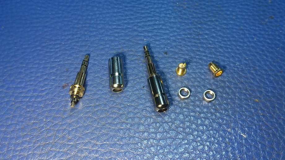
What you need:
1) HD700 2.5mm TRS extended adapter, a pair.
2) MMCX socket, short screw-on type, 1 pair
3) 2 pair of short wires, an inch or so each. I use Estron cable here.
4) Glue. I use UV glue here.
5) Soldering supply
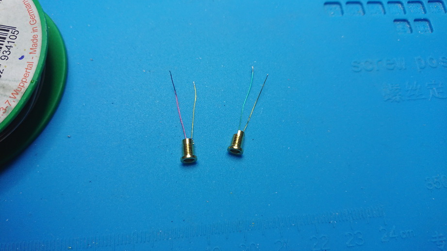
First, solder the wires to the MMCX socket. Note that you can only use the 'short' version of this kind of socket as the long version will be too long for the 2.5mm TRS adapter.
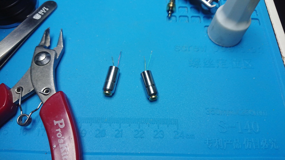
This is the tricky bit - You need to put the nuts into the 2.5mm TRS housing, then try to screw the MMCX socket in until they are tight. It is actually not quite as easy as it seems as the nuts is just a tab smaller than the inner diameter of the housing, so it will want to free spinning around with the MMCX socket instead of trying to screw itself tight. Just know that it can be do - once it is tight, you want to affix them in place so they'll never come loose again. use a tiny drop of UV glue on the inside. Becare not to use too much glue here.
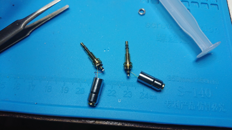
This step is easy, just solder the wires to the 2.5TRS jack. It takes about 3 rotation to screw the TRS into the housing, so I twist the cable anti-clockwise first, then screw the TRS in which the wires to untwist themselves on the inside.
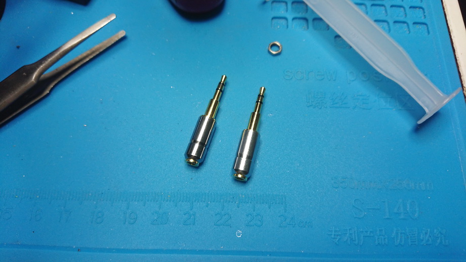
Done.
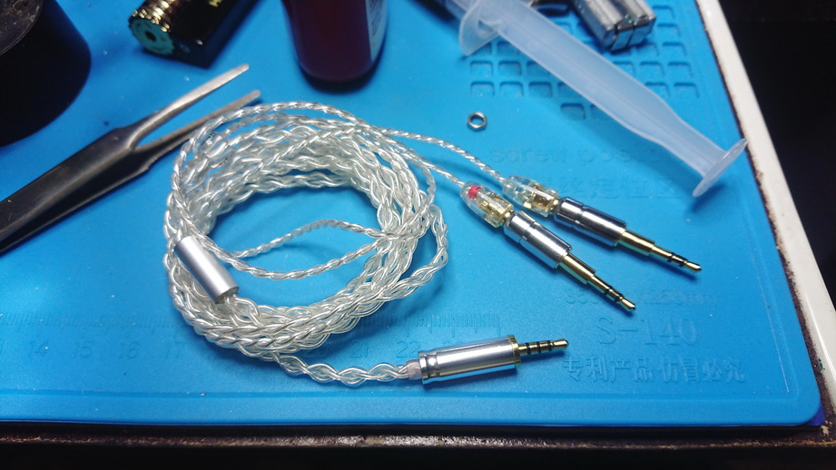
Here is how it looks with MMCX balanced cable.
Afterthought: This project looks simple enough, but the trick bit of securing the MMCX socket inside almost ruin one of the 2.5mm TRS jack. I were lucky that I have managed to salvage the parts and rebuild it again, otherwise the whole project will have to go into the bin. Given the difficulty, I am not sure I'll recommend others to try this - build a whole cable will be a lot easier.

What you need:
1) HD700 2.5mm TRS extended adapter, a pair.
2) MMCX socket, short screw-on type, 1 pair
3) 2 pair of short wires, an inch or so each. I use Estron cable here.
4) Glue. I use UV glue here.
5) Soldering supply

First, solder the wires to the MMCX socket. Note that you can only use the 'short' version of this kind of socket as the long version will be too long for the 2.5mm TRS adapter.

This is the tricky bit - You need to put the nuts into the 2.5mm TRS housing, then try to screw the MMCX socket in until they are tight. It is actually not quite as easy as it seems as the nuts is just a tab smaller than the inner diameter of the housing, so it will want to free spinning around with the MMCX socket instead of trying to screw itself tight. Just know that it can be do - once it is tight, you want to affix them in place so they'll never come loose again. use a tiny drop of UV glue on the inside. Becare not to use too much glue here.

This step is easy, just solder the wires to the 2.5TRS jack. It takes about 3 rotation to screw the TRS into the housing, so I twist the cable anti-clockwise first, then screw the TRS in which the wires to untwist themselves on the inside.

Done.

Here is how it looks with MMCX balanced cable.
Afterthought: This project looks simple enough, but the trick bit of securing the MMCX socket inside almost ruin one of the 2.5mm TRS jack. I were lucky that I have managed to salvage the parts and rebuild it again, otherwise the whole project will have to go into the bin. Given the difficulty, I am not sure I'll recommend others to try this - build a whole cable will be a lot easier.
Last edited:
Users who are viewing this thread
Total: 3 (members: 0, guests: 3)

