
nightanole
100+ Head-Fier
- Joined
- Dec 24, 2008
- Posts
- 325
- Likes
- 10
Well i got all the parts in for my CK2III build. However headwiz is still down, and i cant find a build thread here like the M3. Is there one?
Anyway i have a few questions if some one could help.
1. Im popping in the wee little transformer inside the case for an all in one setup. Its been ingrained in my skull not to mount the tor with a center screw to the chassis. If that is the case how should i mount the unit to the case (hot glue?)
2. I used a shunt style volume control on my starving student and it seemed to really help the super cheap volume control sound good. I was wondering if I could use that style with the blue alps, or should i just stick to stock since its a special $16 unit? In theory if i used a 50k resistor, the source would only see 50k or higher, but the the unit would see variable 100k to 50k instead of a fixed 50k. This would also knock the gain down from 9 to 5, which is fine for my 64ohm or under phones.
shunt style volume control
3. Can the unit be sealed and still use the 30ma quiescent current? I ordered 6 heatsinks instead of just the 2 output ones. Not sure what good a heatsink is gonna do with no air flow though.
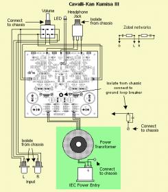
4. Guess i should have read alittle further in the build up. it says that if i place the transformer in the case, and use earth ground, i will create a ground loop so i should connect the ground of the board to the chassis via "10Ω 5W wirewound resistor in parallel with a 0.1µF film capacitor rated at least 250VAC". This is what doesnt make sense. If i would have just used a jamaco wall wart maker, and placed the transfomer in that, i wouldnt run a earth ground to chassis, and then i just ground the board to the chassis. So why do i have to connect earth ground to chassis when its in the box? cant i just make it a standard 2 prong device?
Anyway i have a few questions if some one could help.
1. Im popping in the wee little transformer inside the case for an all in one setup. Its been ingrained in my skull not to mount the tor with a center screw to the chassis. If that is the case how should i mount the unit to the case (hot glue?)
2. I used a shunt style volume control on my starving student and it seemed to really help the super cheap volume control sound good. I was wondering if I could use that style with the blue alps, or should i just stick to stock since its a special $16 unit? In theory if i used a 50k resistor, the source would only see 50k or higher, but the the unit would see variable 100k to 50k instead of a fixed 50k. This would also knock the gain down from 9 to 5, which is fine for my 64ohm or under phones.
shunt style volume control
3. Can the unit be sealed and still use the 30ma quiescent current? I ordered 6 heatsinks instead of just the 2 output ones. Not sure what good a heatsink is gonna do with no air flow though.
4. Guess i should have read alittle further in the build up. it says that if i place the transformer in the case, and use earth ground, i will create a ground loop so i should connect the ground of the board to the chassis via "10Ω 5W wirewound resistor in parallel with a 0.1µF film capacitor rated at least 250VAC". This is what doesnt make sense. If i would have just used a jamaco wall wart maker, and placed the transfomer in that, i wouldnt run a earth ground to chassis, and then i just ground the board to the chassis. So why do i have to connect earth ground to chassis when its in the box? cant i just make it a standard 2 prong device?
