Cavalli EHHA Embedded Hybrid Headphone Amp
Oct 22, 2009 at 1:29 PM Post #1,036 of 1,823
Runeight will have to weigh in - but I think you are going way overkill with 4 sigma22s. The output devices won't draw/handle the amount of juice they'll generate.This amp, while it performs in the b22 league, is NOT designed to draw like 4 b22 boards.

Cut two out and spend the money on a great stepped attenuator...
 
Oct 22, 2009 at 1:45 PM Post #1,037 of 1,823
Can't find the calculator - but here's the simplified gain formula:


Quote:

Originally Posted by wiatrob /img/forum/go_quote.gif
So, can I be safe in assuming that for this amp:

Gain = 1/[R13/(R12+R13)]


Oct 22, 2009 at 2:36 PM Post #1,038 of 1,823
Quote:

Originally Posted by wiatrob /img/forum/go_quote.gif
Runeight will have to weigh in - but I think you are going way overkill with 4 sigma22s. The output devices won't draw/handle the amount of juice they'll generate.This amp, while it performs in the b22 league, is NOT designed to draw like 4 b22 boards.

Cut two out and spend the money on a great stepped attenuator...


Hey, I'm all for saving money. I just want to make sure I don't over tax the S22. I've seen some people around here build a 2 channel B22 that runs speakers off of 1 S22. I didn't realize that the B22 draws so much more power than the EHHA.

According to the EHHA website the 2.5" heatsinks are adequate for speaker duty, however my calculation show that it is coming close to max Junction temp for the mosfets.

There is one piece of info that I don't know to calculate the value accurately: How much voltage is across the mosfets?

I used 22V but that may not be accurate.
 
Oct 22, 2009 at 6:49 PM Post #1,039 of 1,823
Quote:

Originally Posted by wiatrob /img/forum/go_quote.gif
Can't find the calculator - but here's the simplified gain formula:


Champion! Thanks wiatrob
smily_headphones1.gif
 
Oct 23, 2009 at 3:11 AM Post #1,040 of 1,823
Quote:

Originally Posted by johnwmclean /img/forum/go_quote.gif
Champion! Thanks wiatrob
smily_headphones1.gif


No problem - Solve for your target R's and pick the next closest common resistor value...
 
Oct 23, 2009 at 3:48 PM Post #1,041 of 1,823
Quote:

Originally Posted by jjazzyj /img/forum/go_quote.gif
my calculation show that it is coming close to max Junction temp for the mosfets


Hopefully your calculation is wrong. The maximum I'd ever run a device would be half of the max junction temperature. Care to show your math?
 
Oct 23, 2009 at 5:50 PM Post #1,042 of 1,823
Quote:

Originally Posted by luvdunhill /img/forum/go_quote.gif
Hopefully your calculation is wrong. The maximum I'd ever run a device would be half of the max junction temperature. Care to show your math?


I = √(Po / 8)

P=V * I

Tj = Ta + (P * (Rjc + Rcs + Rsa))

Po=18W
Rjc=3.3C/W
Rcs=.9C/W
Rsa=2.6C/W
V=22V (voltage across mosfets, B22 example)
I=1.5
Ta=40C
P=9.9W


I've assumed that playing real music I'll only be using 30% of the current calculated which makes I=.45 instead of 1.5.

Tj=107.32C

Max Junction temp of the Mosfet is 175C

So my initial calc was a a little off as it showed 165C.

It is entirely possible for the internal temp of the chassis to exceed 40C which would be cutting it close IMO.

I am planning a perforated metal top, so that may never happen.
 
Oct 23, 2009 at 6:24 PM Post #1,043 of 1,823
I believe this number if you're using the EHHA as a speaker amp??

A while back in the thread I'm pretty sure that I mentioned that external heatsinks would be needed for speaker duty. My apologies if this comment did not reach you. I know it is not mentioned on the website which only considers the amp as a headphone amplifier. Hopefully, this doesn't make a whole lot of build trouble for you.
frown.gif
 
Oct 23, 2009 at 6:50 PM Post #1,044 of 1,823
I reluctantly returned the EHHA to wiatrob Wednesday. I highly recommend the EHHA to any DIY'ers out there.

To summarize - It's a great amp with my balanced phones (HD600/800 and K1000), that has better soundstage and separation than my WA6 (using SE adapter with same phones), and beats my WA6 and ZDT with K1000 due to better power and control. Bill says it's good for about 18 watts as it is configured. So, I don't know if it is very good with IEM like the WA6 because my IEM are not balanced, but I suspect the gain would be too high for them.
 
Oct 23, 2009 at 7:25 PM Post #1,045 of 1,823
Quote:

Originally Posted by runeight /img/forum/go_quote.gif
I believe this number if you're using the EHHA as a speaker amp??

A while back in the thread I'm pretty sure that I mentioned that external heatsinks would be needed for speaker duty. My apologies if this comment did not reach you. I know it is not mentioned on the website which only considers the amp as a headphone amplifier. Hopefully, this doesn't make a whole lot of build trouble for you.
frown.gif


The website actually mentions 2.5" heatsinks for speaker duty.

Heatsinks

* For headphone amplifier use use Wakefield 647-15ABP or equivalent.
* For speaker amplifier use Wakefield 647-25ABP or equivalent.

According to the calculations in my previous post they should be okay as long as I don't crank it too much. I do have some salvage heatsinks that I could use.

SNC00042.jpg


Probably excessive. They're from old tv broadcast tower equipment.


EDIT: I found the post you were referring to. It details the resistor changes that need to happen as well (beyond the 2W resistor changes). You mentioned that the 2.5" heatsinks would be ok and my previous post more or less indicates the same. Though if I started to stray beyond the 30% too much external heatsinks would be required. You also mentioned that one S22 is ok for 1A peaks. My previous calculations indicate a peak of 1.5A for the full 18W but that might not ever happen. If I found I was running into issues I could always add an S22 later.

Thanks for pointing me in the right direction!
 
Oct 25, 2009 at 3:25 AM Post #1,046 of 1,823
Going through the initial setup and getting 29v on R3, R4 on both of my boards. Anything specific I should look at?
Unfortunately, I already soldered the opamp so does that mess things up? One board passed the output quiescent current and DC offset checks before I shorted a mosfet. Q9M is gone but what other components should I check? R33 is fine.
 
Oct 25, 2009 at 3:44 AM Post #1,047 of 1,823
umm..are you checking voltage across R3 and R4? Am guessing you have one probe on R3/R4 and the other to ground in which case you will probably see close to rail voltage.

You should be having the probes set on either side of the resistors...can you confirm this?
 
Oct 25, 2009 at 3:54 AM Post #1,049 of 1,823
In my opinion, those heat sinks are woefully small. Also, the fin orientation doesn't help much either. I would not run the devices anymore than half their max junction temperature, as stated above. I know for example Nelson Pass has been known to quote the same estimate, and it's a good one.

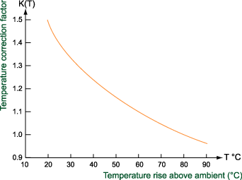
There are a few flaws in your calculations. You aren't considering the thermal resistance of the isolator and/or thermal compound. Also, the thermal resistance of the heat sink is not constant across its operating temperature. Thus, you may need to derate the quoted spec, depending at what ambient temperature it was given. Here is one manufacturers derating curve:

graph-2.gif


If you're looking for a number, I'd recommend something in the 0.5 C/W range, per channel. Perhaps you can inquire what size Conrad heat sink Farrari is using, it looks to be about the right size and fin orientation.
 
Oct 25, 2009 at 4:06 AM Post #1,050 of 1,823
Quote:

Originally Posted by liwei /img/forum/go_quote.gif
Oh, sorry. I was checking relative to ground. I think it was about .6v across R3 and R4. I'll check the boards again later when I get a new fuse.


yeah...good strategy.

That Q9M really is a PITA...well it was for me at least..i ended up blowing a half a dozen of them due to various reasons, only on one particular board though. Once you have it going though, the amp is rock steady.
 

Users who are viewing this thread

Back
Top