Carrie USB-Powered Headphone Amplifier
Jul 11, 2010 at 11:01 PM Post #811 of 913


Quote:
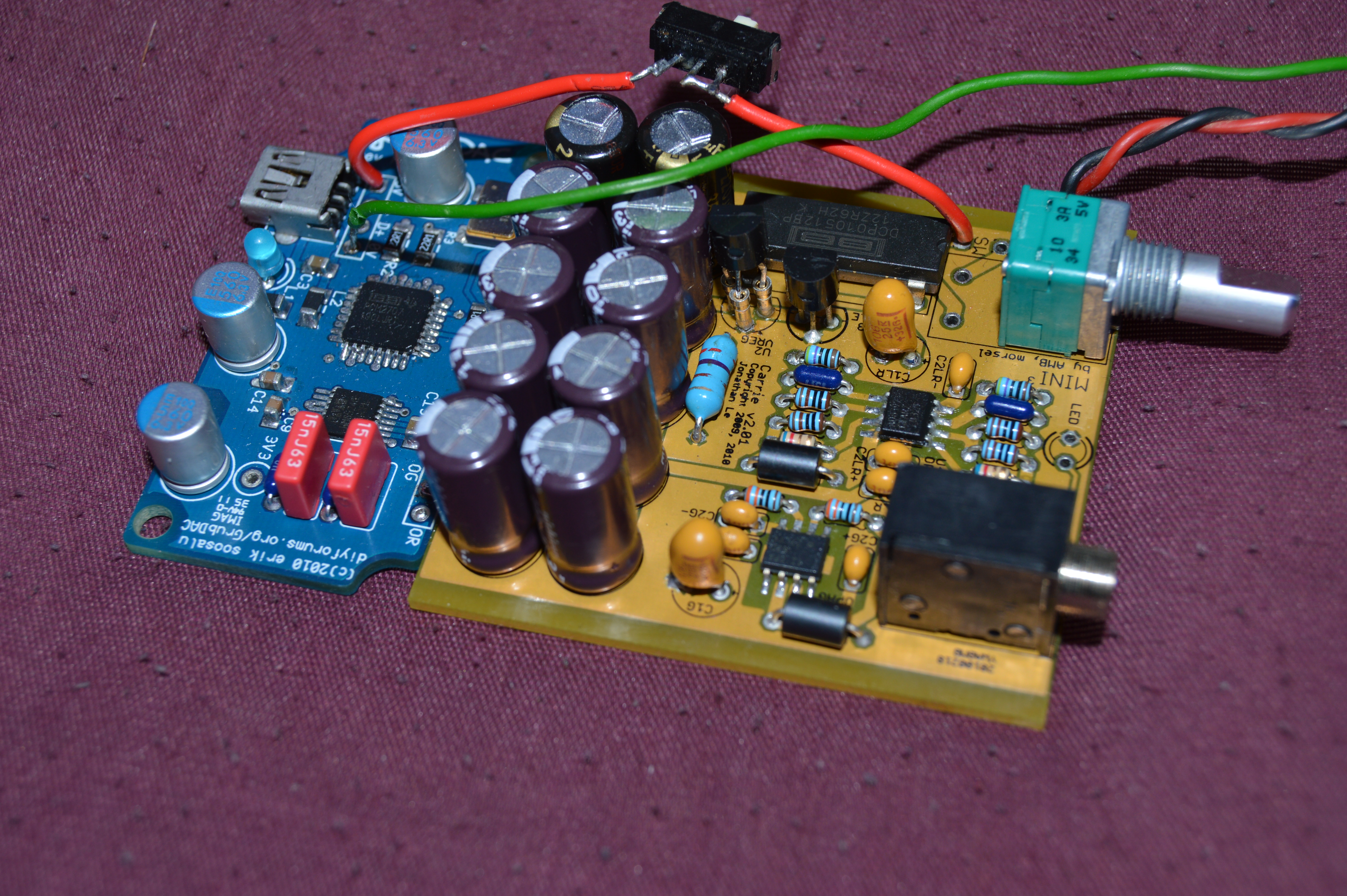
Search the thread - someone has already built a gamma1/Carrie combo.  There was a part change they had to make on the gamma1 or the Carrie will not start.


thanks, yeah I found that post.  I guess what I was trying to find out was, if the power from the gamma1 was regulated, would it have a surge like the carrie would.  But since now i know the carrie is hooked straight up to the USB's power, that seemed to be what was causing problems.  Having the Carrie feed from Gamma1's modified regulated voltage and current, I'm hoping I can avoid this.  Thanks everyone =)
 
Jul 22, 2010 at 12:27 AM Post #812 of 913
Hey all,
 
Check out this thread. 
smile_phones.gif

 
http://www.head-fi.org/forum/thread/503428/carrie-amp-group-buy-2
 
Sep 5, 2010 at 10:15 PM Post #815 of 913
I should also note that my final version of the Carrie + bantam box works completely fine on my MacBook Pro 13" (mid-2010) and Carrie's MacBook. I suspect it still won't work on some MBs, but just an FYI.
 
Oct 12, 2010 at 2:13 PM Post #817 of 913
Will 20mm tall caps fit in the spec'd Hammond case? The C-C1+/-,C2-C7 caps are backordered at Mouser and a comparable part at Digi-key is only available in 20mm height. I apologize if this question has been asked and answered before...I did a quick search but found nothing. Thanks!
 
Oct 18, 2010 at 8:57 PM Post #819 of 913
Just because the part at Mouser is backordered doesn't mean there aren't other suitable caps at Mouser. For future reference, the product pages at Mouser also have a "Find Similar" button on the bottom left. The dimensions required are 8mm diameter x 15mm height at 16V. Typical capacitance values are 330uF, 470uF and sometimes 680uF, but 470uF should be fine. Any more might have too much inrush current with this design.
 
Oct 18, 2010 at 9:07 PM Post #820 of 913
for the schematic in the third post, is it a 12v output from the power part at the top right? from what i read of the thread that's what was the target right, 12v supply -> +/- 6v supply with the virtual ground?
 
also, is the bank of capacitors necessary between v+/gnd and gnd/v-? on tangent's site's page on virtual ground circuits he only has the capacitor between v+/v- for the one using a tle.
 
Oct 18, 2010 at 10:28 PM Post #822 of 913
whoops i left that out of my original question / wording was pretty bad. i meant that bank of capacitors after the tle going from v+ to the tle virtual ground and from there to v-; on tangent's site the virtual ground circuit using a tle does not have those capacitors, it only has a capacitor from v+ to v-. that's where my confusion/curiosity is coming from
redface.gif

 
Oct 19, 2010 at 9:21 AM Post #823 of 913


Quote:
Just because the part at Mouser is backordered doesn't mean there aren't other suitable caps at Mouser. For future reference, the product pages at Mouser also have a "Find Similar" button on the bottom left. The dimensions required are 8mm diameter x 15mm height at 16V. Typical capacitance values are 330uF, 470uF and sometimes 680uF, but 470uF should be fine. Any more might have too much inrush current with this design.


Thanks for the reply. After asking that question, I actually re-visited the BOM on your web site and found that the 470uF would be a suitable replacement, and probably a good compromise with regards to the inrush current. I took the time to read through a lot of this thread and realized the values for those caps don't have to be 680uF.
 
I'm about to start on my Grub, then I'll be waiting patiently (and excitedly) for the Carrie boards to arrive
smily_headphones1.gif
Thanks for putting together the latest group buy!
 
Oct 21, 2010 at 4:11 PM Post #824 of 913
can someone shed some light on what C9-20 are for? i thought the capacitance was only needed from v+ to v-
redface.gif

 
also, i'm thinking about making one of these but to be used without a dac, so i was thinking of switching R1L/R/G with a dc filtering cap and maybe adding a bass boost. bass boost being a pot parallel with a cap, placed in series between R4L/R and the output (i think that's where it goes); this wont increase my current draw by too much will it?
 

Users who are viewing this thread

Back
Top