Carrie USB-Powered Headphone Amplifier
Jun 19, 2009 at 11:16 PM Post #136 of 913
That's great sounds like an easy fix.

DKJones96, did you finish yours yet? How is it going, is it making sound yet?
 
Jun 27, 2009 at 5:06 AM Post #138 of 913
I just got my resistors today. They did indeed arrive as expected, but no one was home to receive the package. I only had enough time today to get it, so expect the completed amp sometime soon. I'll be picnicing all weekend, but I should have something sometime later (learning to be more careful with my promises
tongue.gif
).
 
Jun 27, 2009 at 1:05 PM Post #139 of 913
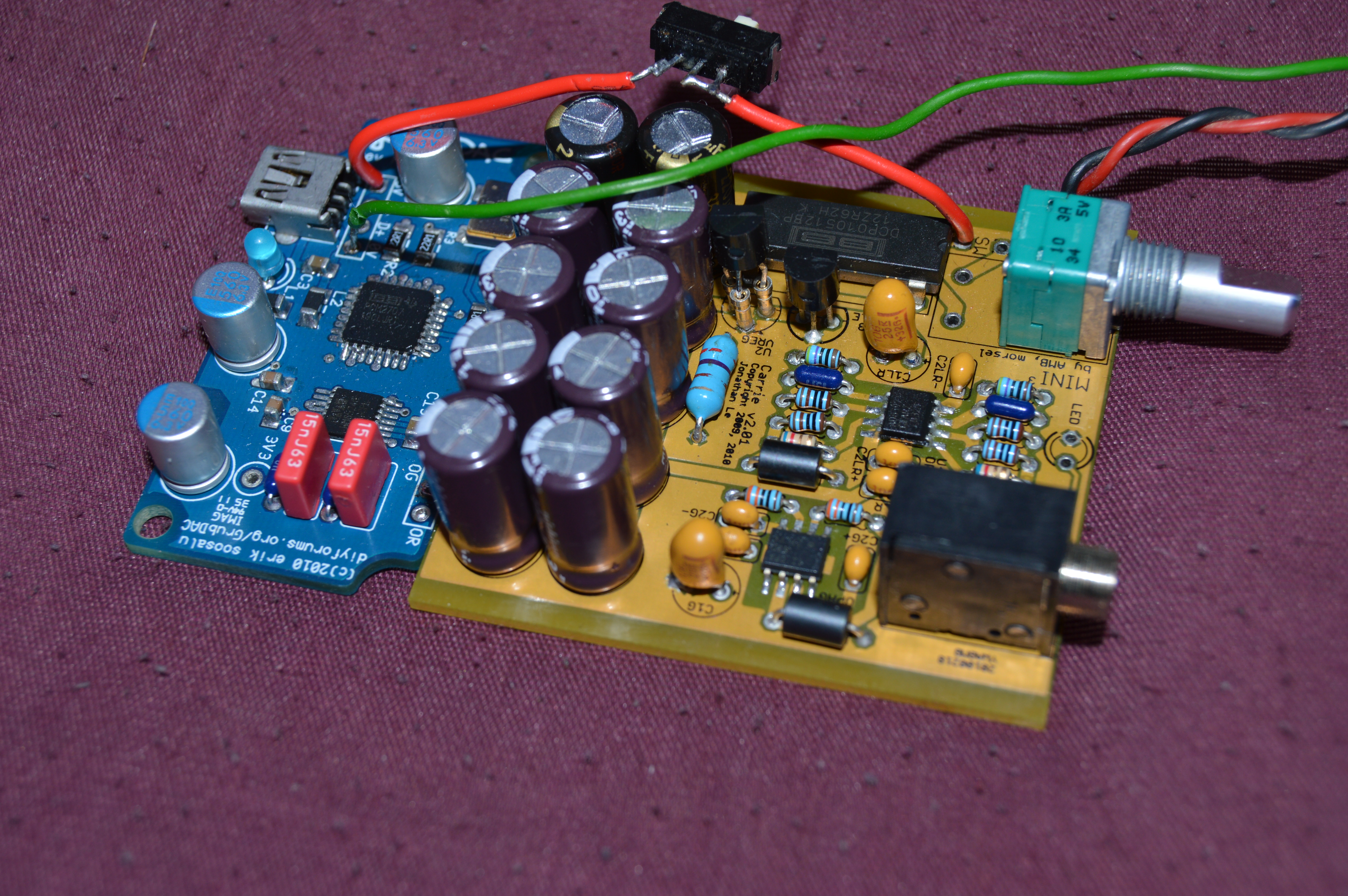
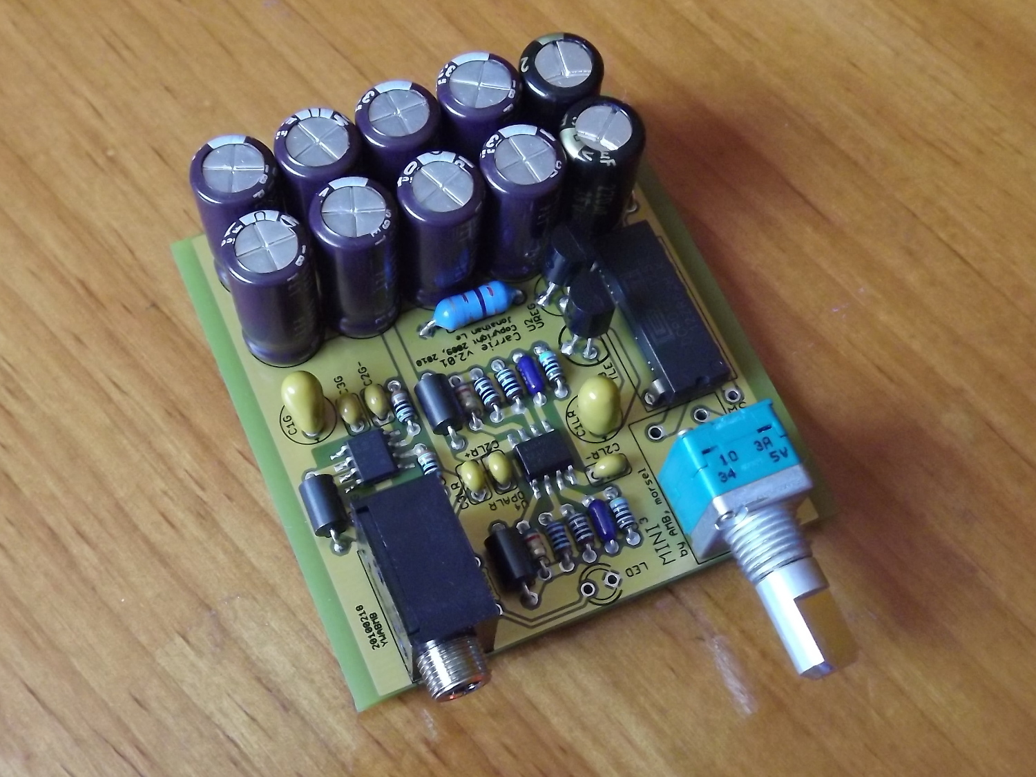
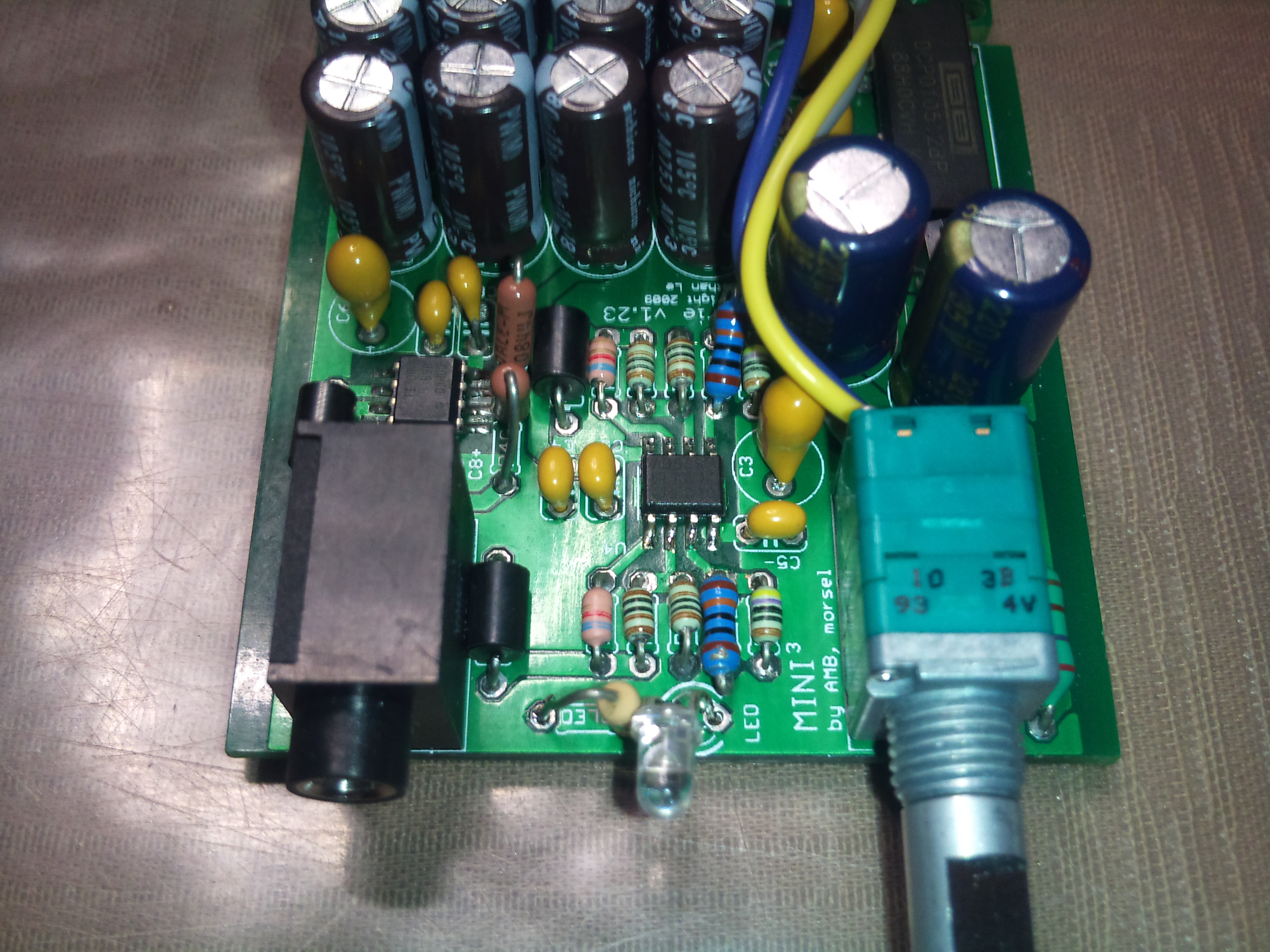
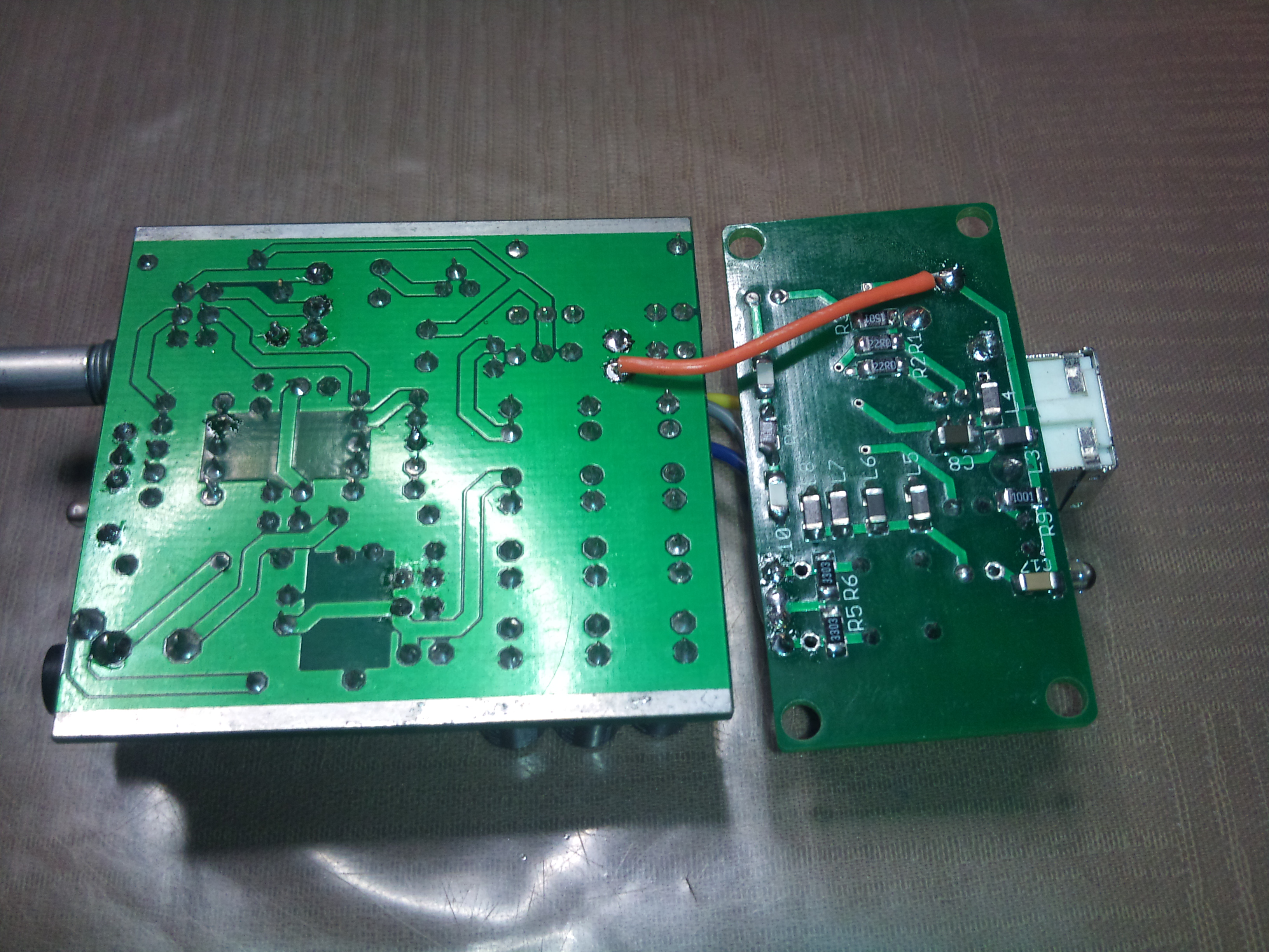
Okay, so honestly, I couldn't wait until this morning to switch out the resistors. I'm pleased to announce a fully working Carrie! I'll have to wait to get my BantamDAC built up though, but nevertheless, it's a nice feeling to listen to an amp that I designed (more or less
redface.gif
) and built. Yay!

I'm still waiting for prototyper comments, so I'm not going to finalize a design yet. I am still tweaking the power supply according to what I felt should be changed, but I'm still eager to hear what others think of the build difficulty and such. I feel I'm getting the hang of EAGLE, so it's going to be less difficult and more fun using it. And as grateful as I am to MrMajestic2 for letting me get on board (pun intended) with his order, I'm not all that pleased with the build of the PCB. I had to rework a few pads, and most of them fell off the board. Humbug. Alas, one more prototype run, and then off to production we go.

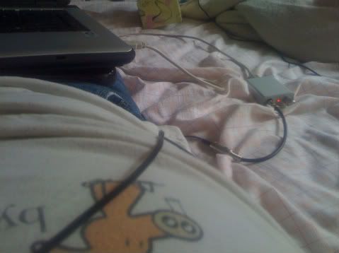
Ah yes, the sweet sound of music. It's currently hooked up to my iPhone 2G and I'm listening through my Shure E4Gs. Success!

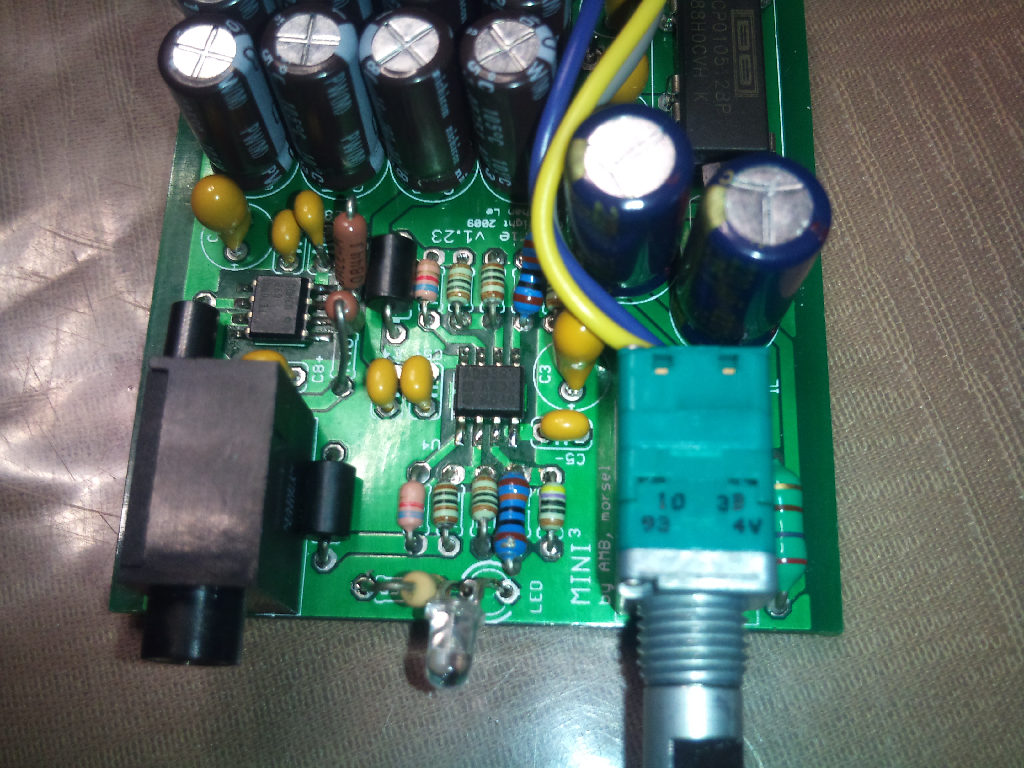
edit: Of course, thanks go to AMB for allowing me to lift, at least temporarily, the schematic, layout and name of the Mini^3 for the design. We'll still have to see how it measures, but that will come with time. If not, I'll just have to remove the Mini^3 name from the board.
 
Jul 3, 2009 at 5:08 AM Post #142 of 913
Well, I have a successful pairing of a Bantam and a Proto Carrie. Works great, sounds great too. My voltage out of the converter is only 7.5 volts or so though, so maybe I have something a little goofy yet. Will post pics tmw.

Edit: I measure +4.89v and -4.89v at the appropriate pins on both Opamps. I must have done something right. Although I havent even looked at the schematic for this, so I maybe that 7.5v is ok.
 
Jul 3, 2009 at 1:02 PM Post #144 of 913
Looks really good. I want one!!!
 
Jul 3, 2009 at 1:41 PM Post #145 of 913
Thanks, Tom and Billy.
smily_headphones1.gif


Quote:

Originally Posted by Gross /img/forum/go_quote.gif
Well, I have a successful pairing of a Bantam and a Proto Carrie. Works great, sounds great too. My voltage out of the converter is only 7.5 volts or so though, so maybe I have something a little goofy yet. Will post pics tmw.

Edit: I measure +4.89v and -4.89v at the appropriate pins on both Opamps. I must have done something right. Although I havent even looked at the schematic for this, so I maybe that 7.5v is ok.


Thanks for getting yours up and running so quickly, Brian.
ksc75smile.gif


Which pin are you using as reference for that 7.5V reading? If you measure between TP5 (GND) and TP2 (the output voltage of the DCP), then you should get that 7.5V. If you measure between TP6 (V-) and TP2, you should get something like 12.89V. Between TP6 and TP4, you'd measure 9.78V. For the next version of the board, I'm renaming the test points from TPx to what they actually represent: V+, V-, 12V, 12F(iltered), 5V and 0V. That way we can avoid this kind of confusion.
tongue.gif
Keep in mind that the DCP is isolated, and USB GND, aka input V-, is connected to the midpoint of the output.
 
Jul 3, 2009 at 2:22 PM Post #146 of 913
Quote:

Originally Posted by joneeboi /img/forum/go_quote.gif
For more gory photos, check out,

Picasa Web Albums - joneeboi - Carrie

Enjoy.
smile_phones.gif


Great little design and well executed, really like it.

When do you think you will have production boards ready? I don't really need another portable, but like this so much I may not be able to resist. I have a spare Bantam board in my parts box, I think it may have found a home.
 
Jul 3, 2009 at 3:13 PM Post #147 of 913
I don't know when production will take place. I can't imagine how long it will take to reel in all the suggestions from the prototypers, and I don't know how strict to be on deadlines. I don't want to force anything just to rush it out the door though. Once I feel comfortable with the improvements and the state of the design, I'll get it prototyped at least once more, and then I'll put the finishing touches on it before getting it fabbed. If there's enough interest, perhaps we can do a group buy so that I won't break the bank.
redface.gif
 
Jul 6, 2009 at 10:54 PM Post #149 of 913
Are you planning on merging the two PCB's, or keeping them separate?

If I build this, I think I might try to squeeze line-in and line-out into it. I'm not sure it's really necessary to add to the PCB though.
 
Jul 6, 2009 at 11:20 PM Post #150 of 913
I was looking at the psm2707 datasheet and it has a VCOM output on pin 32 which is half of the 5V (or 4.75V regulated) which would be should be the same DC level as the left and right channels. Since the mini3 is a 3 channel design, couldn't you somehow connect the ground channel to the common/half voltage and eliminate the output caps? Basically, if you set the mini3 ground to 2.5V relative to the USB bus, I think you could eliminate the DC offset.

Is this correct?
 

Users who are viewing this thread

Back
Top