Carrie USB-Powered Headphone Amplifier
Dec 7, 2008 at 3:37 PM Post #61 of 913
There is always this
tongue.gif
 
Dec 7, 2008 at 4:57 PM Post #62 of 913
Quote:

Originally Posted by cobaltmute /img/forum/go_quote.gif
There is always this
tongue.gif


the foundamental notion of this thread is that 5vpp swing out of a single 5v rail isn't enough.

I think for a lot of occasions, you don't need more than a volt or so to get decent volume. think about it this way: the cmoy that everyone loves uses a chip that can deliver 40ma. that's about 600mv into a 16ohm headphone!

and most people haven't complained about its lack of power or loudness.

I pointed this earlier, in the end, you are likely getting nothing for going to a complicated solution to produce higher rail voltage than what's available straight out of a usb, at the added costs, noise, board real estate and complexity.

often time, a simpler solution is the best / better solution.
 
Dec 7, 2008 at 9:57 PM Post #63 of 913
another approach that I mentioned earlier, if you want high voltage, split rails but don't need isolation, is to get both +/- rails from one single smps.

an example of how this can be done is in the cs5171 datasheet, figure 47 - but the basic concept applies to any other boost converter and you can use any of your favorite boost (or actually buck, if you need to step down) chips.
 
Dec 9, 2008 at 2:54 PM Post #64 of 913
No, I haven't lost interest in this design. I have exams to attend to, so please don't take my silence as my surrender to the design obstacles.

I'm thinking of stepping up to 12V and regulating to 10. With a generous 40mA draw for the opamp and regulator,

40mA * 12V = 0.48W in the booster
40ma * 12V / 5V / 60% = 160mA from the input with a paltry 60% efficiency.

I think that leaves plenty of room. I think there's plenty of current left for a decent two-channel amplifier.
 
Dec 9, 2008 at 8:45 PM Post #65 of 913
Quote:

No, I haven't lost interest in this design. I have exams to attend to, so please don't take my silence as my surrender to the design obstacles.


Same story here. I've got a design using Murata components that will give lots of headroom. I will build it Sunday or early next week.
Unfortunately I might not be able to measure it until January 5th as the prof who I was counting on to let me into the lab will be away over Christmas break.
Anyways I'll post details as it comes together.
 
Dec 12, 2008 at 4:38 PM Post #66 of 913
I just spoke to the lab tech and he'll let me in next week. So I'll be able to do measurements
smily_headphones1.gif

Not sure that anyone's really following this or interested, but just in case there's the update.

I think it'll be handy to have a simple booster schematic, bom, and most importantly measurements. It'll allow people to figure out whether the booster can work for what they want to do and also whether it has the quality they're looking for.
 
Dec 15, 2008 at 4:02 PM Post #67 of 913
I've been doing some thinking, and it might be worth investigating the merit of 5V opamps. There are lots of low-voltage, battery-powered amps out in the wild, eg. cell phones, MP3 players, and a lot of them don't sound all that bad. Even a bunch of DACs are able to drive low impedance headphones, so maybe there's something to the low voltage, rail-to-rail opamps out there. I think this amp board would have enough space for 5V-regulated-to-4.75V opamp operation and a boosted opamp section with the choice belonging to the builder. Will continue to investigate low voltage opamps.
 
Dec 15, 2008 at 6:41 PM Post #68 of 913
I still think the voltage booster idea has merit. I'd rather not make too much of a compromise.

I have one question though. No one seems to use lithium batteries at all. You would think that with a nominal voltage of 3.6v and zero memory everyone would be all over them. I see people state that they only have a 500 recharge limit. Honestly, that is not the case. You can and should charge them anytime you are able to. No waiting for them to discharge. If you don't discharge them all the way (2.8v) which you wont most of them time. They will last many thousands of cycles. Most cellphones use lithium now. I don't see many people complaining about the batteries unless they are the kind that never charge their phone. You will ruin a lithium battery in short order by not keeping it charged.

The charging circuit is very simple and can be built into the amp power supply for home use and there will be no worries about over charging the batteries even if it is plugged in forever. The charger is basically a voltage and current regulated power supply. It has all of five parts. 2xlm317 adjustable regs and 3 resistors.
 
Dec 15, 2008 at 6:59 PM Post #69 of 913
The blowing up issue has people concerned.

Look at the troubles that some people have building their amps as it is, and then look at that in context of something that can blow up.
 
Dec 15, 2008 at 7:04 PM Post #70 of 913
The reason I'm not going with batteries is because I won't be using my DAC/amp box without my laptop, so the only batteries I need are in my laptop. My audio source will be the BantamDAC, and that won't work without the USB. I just wanted to make a decent-quality, USB powered headphone amp that does away with the batteries and whatever minimum hassle there is associated with batteries. If I didn't mind the batteries so much, I'd go with a gamma1+Mini^3 setup like n_maher. All in all, the difference isn't all that great, but combine my desire to design and produce my very own board with my preference for a simple setup in a single Hammond 1455C80x, I will likely continue on this path. In reality, I could just as easily breadboard a preliminary amp running on regulated USB power at 4.75V to an AD8656 since it really is a much simpler solution. Beyond that, I want to see how far one can push the limits of the USB power in terms of higher-quality-than-onboard-soundcard audio since it doesn't seem to be a well-explored route. error401 and MWP are just some members that have completed the circuit, but that is a fairly small proportional of the DIY headphone amp community. Trail-blazing ftw!
 
Dec 15, 2008 at 8:28 PM Post #72 of 913
No, I haven't, but I've always used my laptop by a wall outlet and plan to continue doing so. I realize that there is a potential for plugging in a wallwart for my headphone amp if I'm always by an outlet, but I've carried around a pluggable PIMETA before with my laptop and it was nothing short of annoying with a mix of troublesome. One wire from the wall which is going to be there anyway, one wire from the laptop, one wire to my ears.
 
Dec 16, 2008 at 2:21 AM Post #73 of 913
Quote:

Originally Posted by cobaltmute /img/forum/go_quote.gif
The blowing up issue has people concerned.

Look at the troubles that some people have building their amps as it is, and then look at that in context of something that can blow up.


Again, this is another misconception. The fires that you hear about stem from the manufacturer using the batteries way out of spec or very near the maximum current draw. For most of the amps here we are talking less than 1c draw on a battery that is good for 10 to 20c. Don't forget that most of them now come with PCB protection on the cell from the factory. Most people have one on their hip for 12hours a day. I would say that we are well within the safe zone. LiFe cells are also available. Those where specifically built with safety in mind. The power density isn't at the same level as with lithium polymer but it is a small price for absolute stability.

If you are saying that people might short the battery terminals then obviously you have never shorted the terminals on a Nicd or NiMH battery either because they burn rather spectacularly as well.
 
Dec 16, 2008 at 4:13 AM Post #75 of 913
Quote:

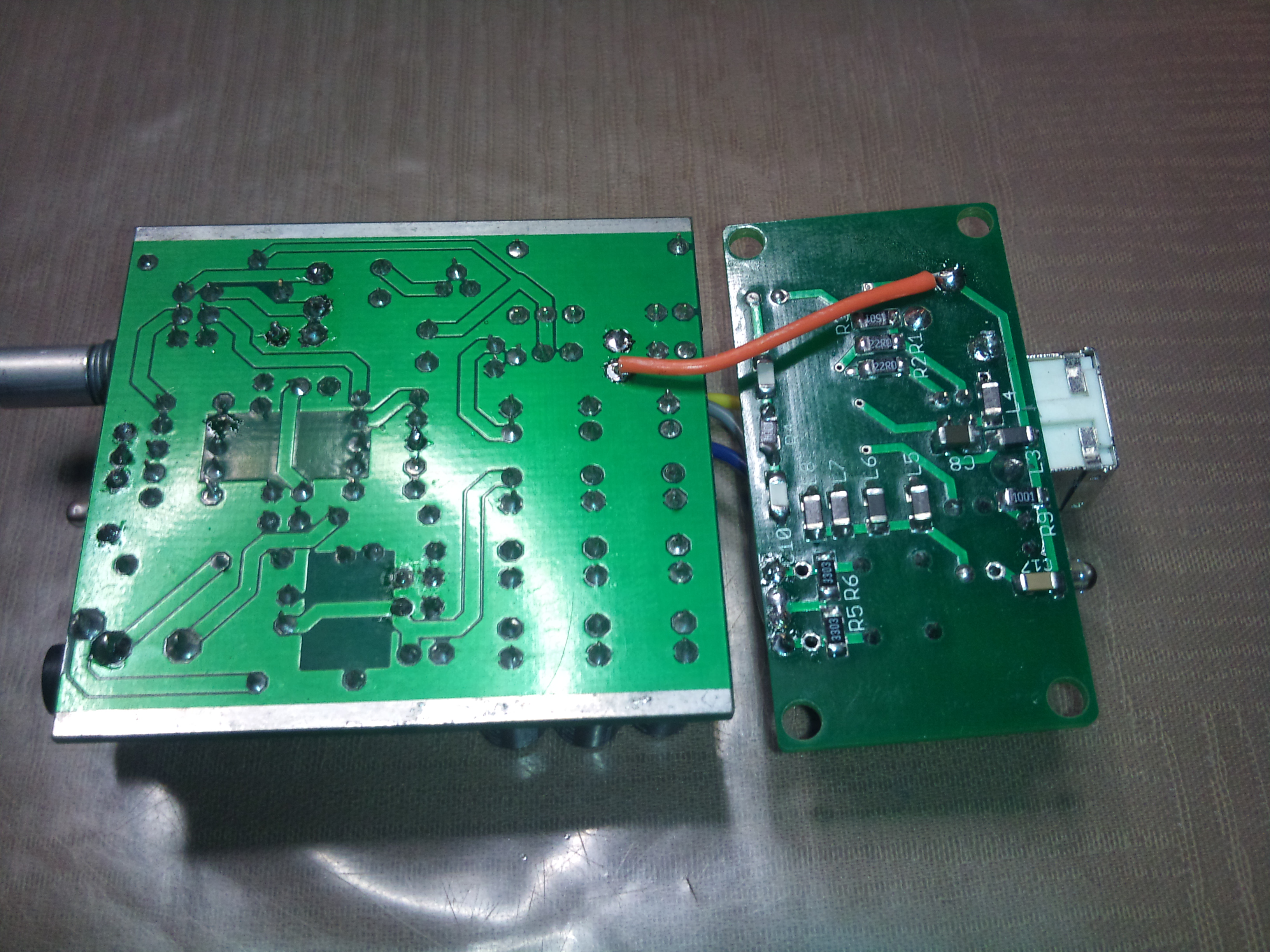
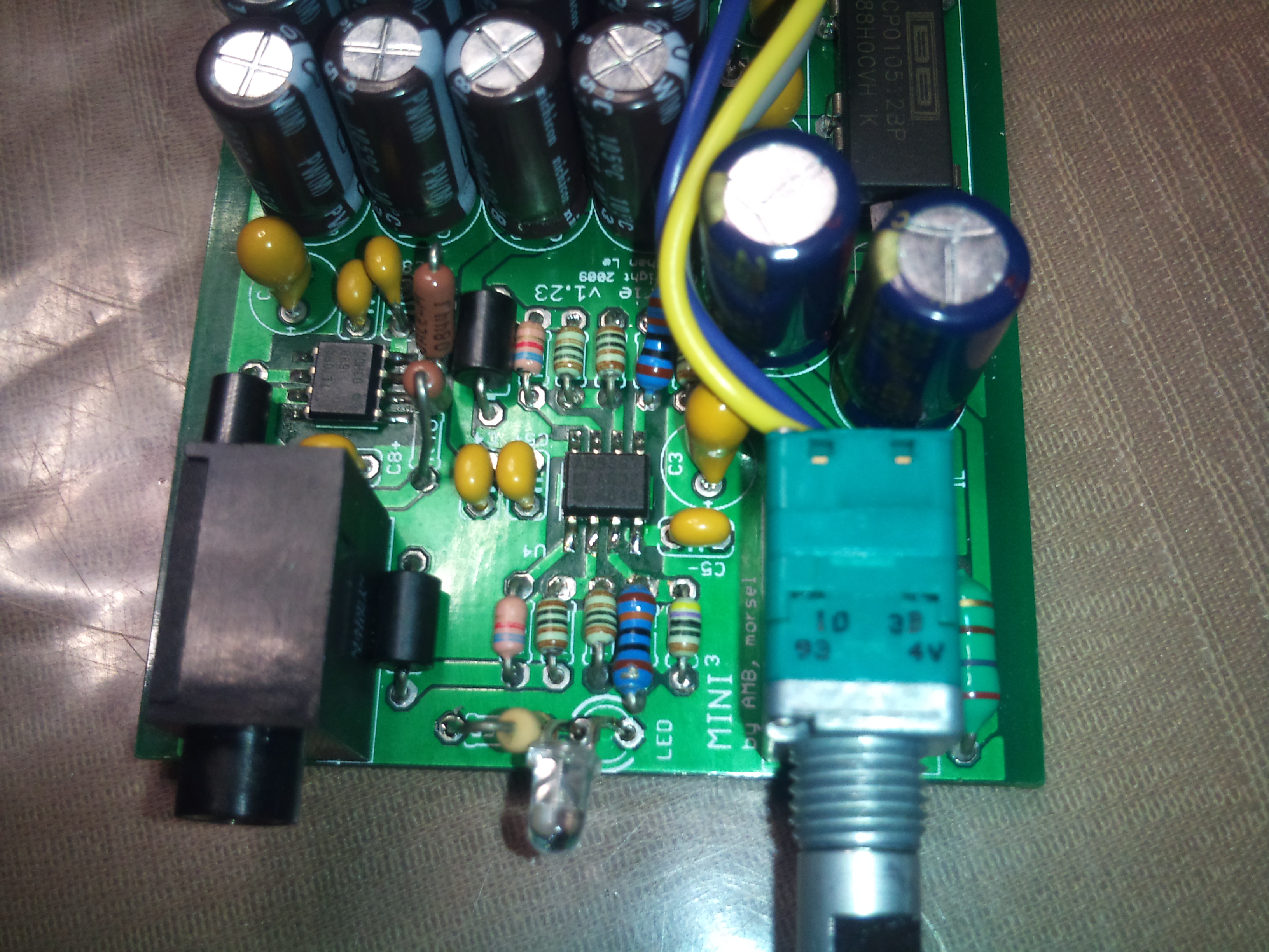
Originally Posted by rembrant /img/forum/go_quote.gif
The charging circuit is very simple and can be built into the amp power supply for home use and there will be no worries about over charging the batteries even if it is plugged in forever. The charger is basically a voltage and current regulated power supply. It has all of five parts. 2xlm317 adjustable regs and 3 resistors.


I don't think I'd ever trust such a circuit to charge a Lithium-based battery. Certainly not in a DIY project I release to the wild. The fact that lithium batteries are more dangerous than other types is absolutely not a myth. They are much more sensitive to charging conditions than most other types, and even over trickle-charging them can start fires. I've considered using them in the past, and may still for my own projects, but I don't think I'd ever release that portion of anything I do in any detail. It's simply too easy to cause damage with this due to build errors, user errors, or just plain clumsy probing or whatnot. The one exception would be 'standard' sized cells that can fit in an external charger and internal battery holder. That would eliminate much of the danger, but it's also much less convenient.

I think I have seen some reports of people using lithium chemistry batteries for portable amps, it's just not something that the mainstream designers have recommended (yet?). My guess is that this is primarily due to the fear of inexperienced DIYers causing serious harm, but the greatly increased complexity of the charging circuit can be a bit size prohibitive in a DIY context as well. As I said, I looked into this, and doing a proper LiIon charger sticking to TH parts was quite large in board area, as was keeping to large pitch SMD. A 'hacked' circuit in such a critical context is unacceptable IMO.

But yea, totally off-topic, sorry to continue to derail the thread, but I've written the post now...
 

Users who are viewing this thread

Back
Top