Carrie USB-Powered Headphone Amplifier
Oct 10, 2009 at 8:18 PM Post #511 of 913
I hate this kind of issue.

I have three mini-USB cables on my desk.

Cable 1: from a WD Passport harddrive
Cable 2: from an old iRiver player
Cable 3: some generic.

Cable 1 and 3 shutdown the port every single insertion. Cable 2, the iRiver one, works every single time. The only difference I can see is that the iRiver one has ferrites at both ends.

ARGH!!!!

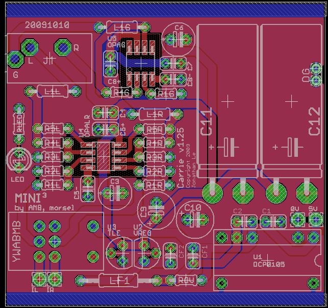
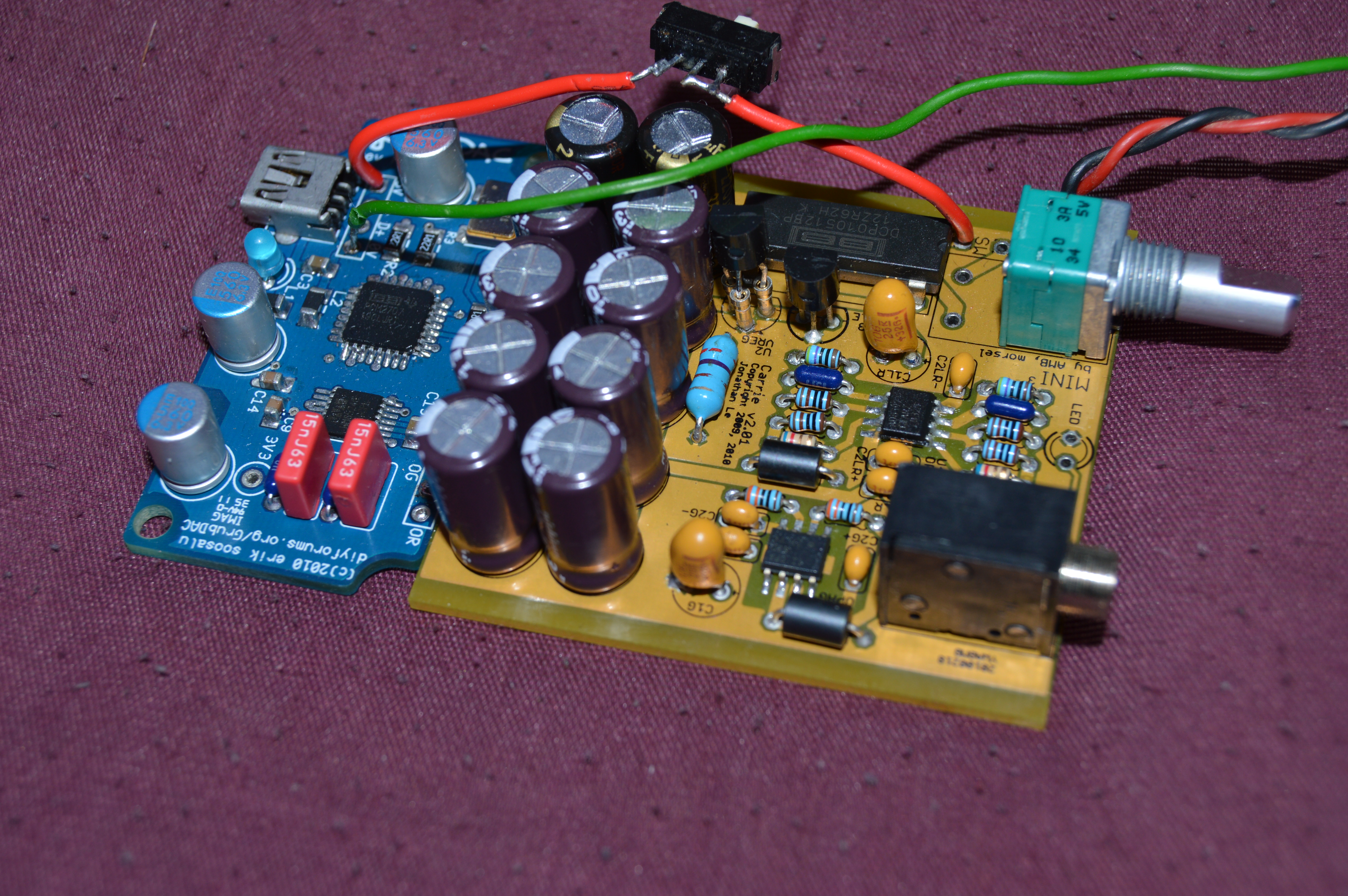
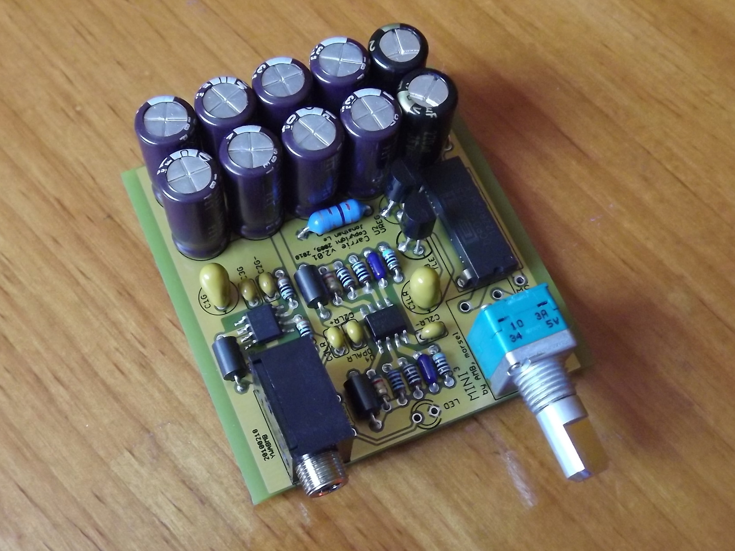
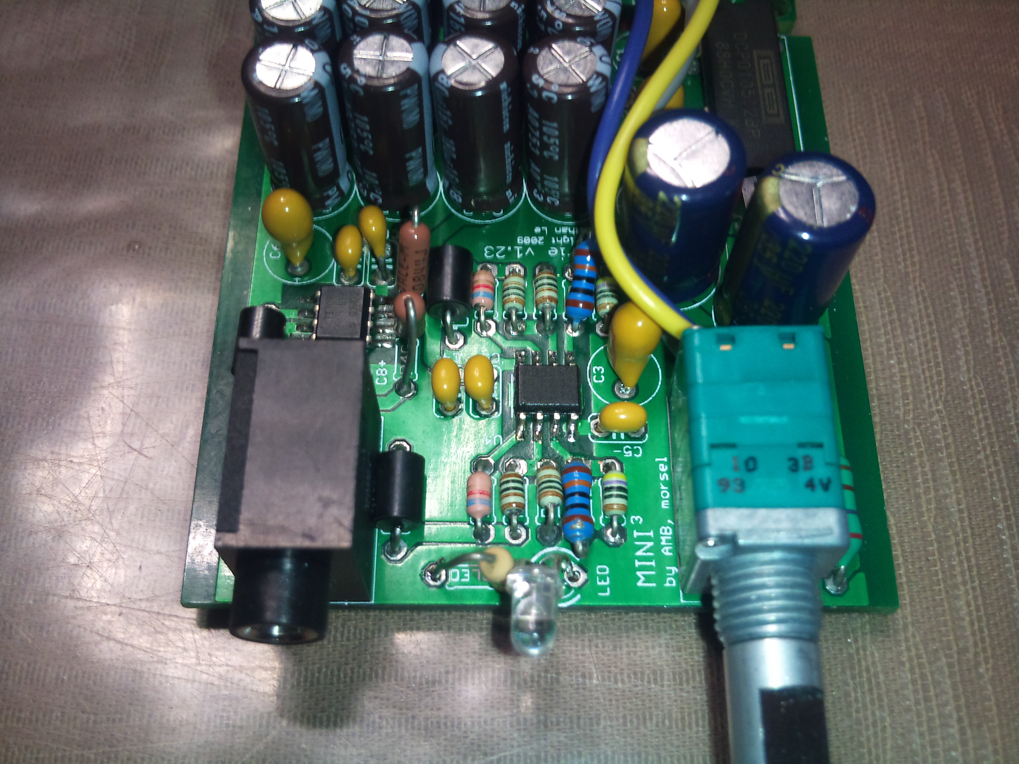
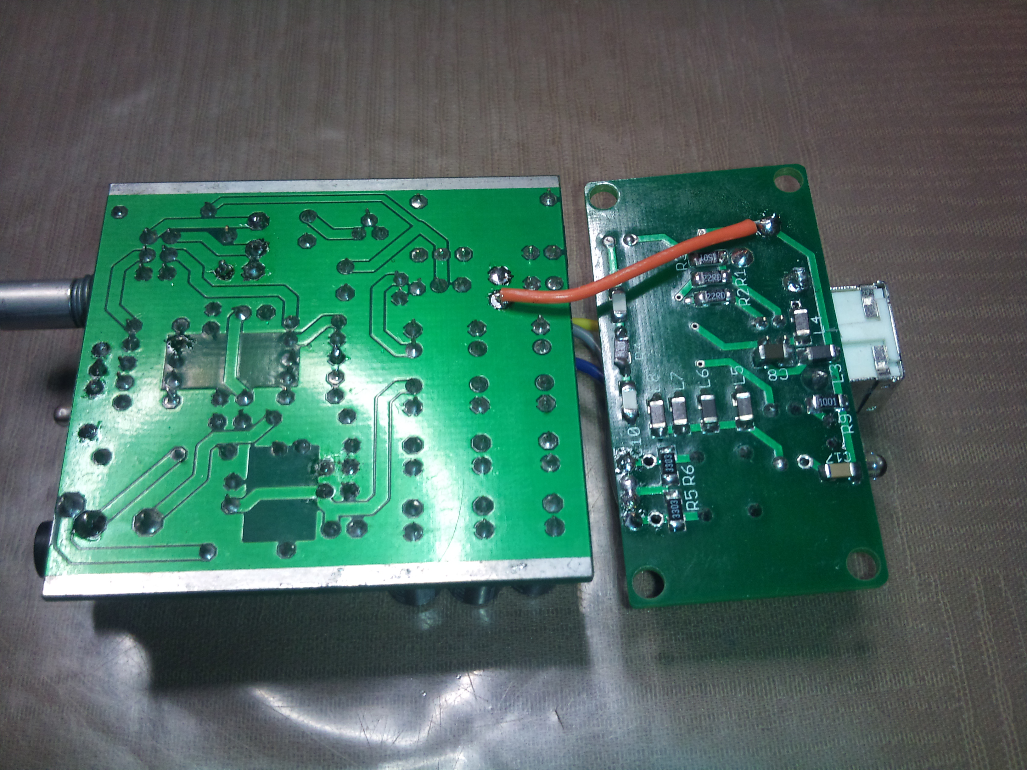
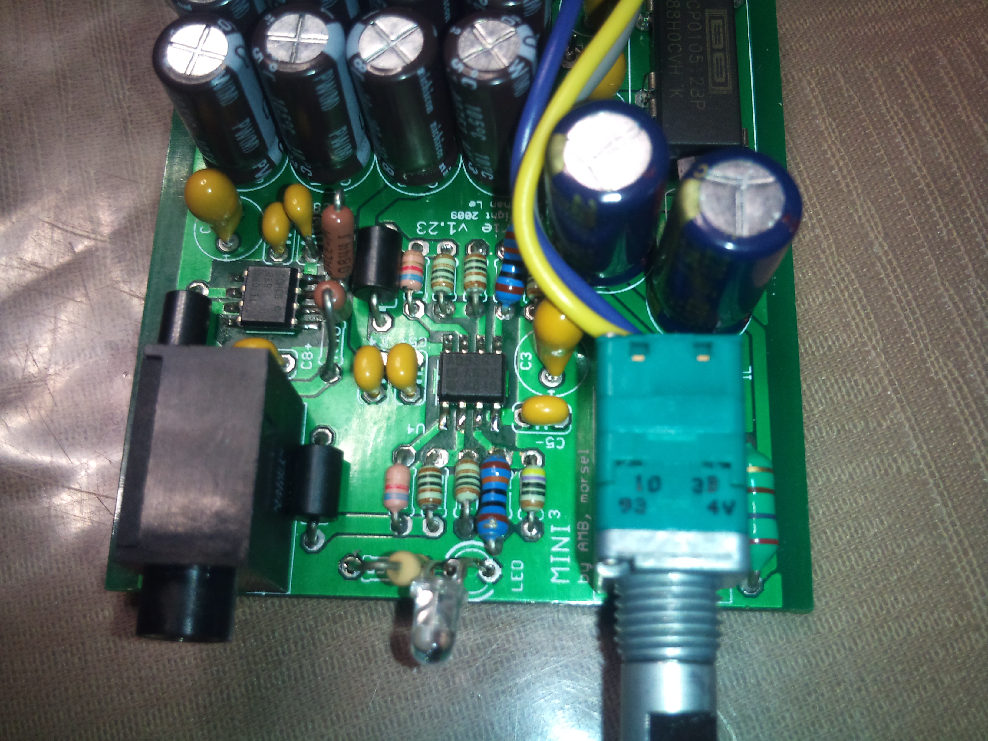
As a further note, this Carrie is setup with close to the BOM I posted earlier. C12-17 were removed and replaced with 2x680µF Panasonic FM caps from rail to rail. So same capacitance, just better utilized.
 
Oct 10, 2009 at 9:23 PM Post #512 of 913
An iRiver cable I have wasn't able to completely power up my laptop hard drive unless I shake it a bit to get the spinning started. I'm thinking something is restricting current or voltage, maybe the ferrite, but it's strange...
 
Oct 10, 2009 at 9:53 PM Post #513 of 913
Has anyone tryed the standard 3 wire cables that come with portable usb hard drives? Ya know 2 A ends and 1 mini end, for the units that require more then 100-500ma inrush current to get the drives spinning. In other news i got my cheap stepped ebay special so i should have my carrie/gamma2 combo working this week.

I still dont get my voltages but i checked with 2 multi meters. unpluged my usb power is 5.1v, plug in the gamma2 and it drops to like 4.5. 4.75tp and 3.3tp on the gamma show 4.3 and 3. But its working.... And ive tested it with 2 multi meters that cost over $200 each... but dont regulators put out nothing if they dont have the min .2v in over regulation voltage???
 
Oct 10, 2009 at 10:00 PM Post #514 of 913
The regulators drop-out ie. they don't regulate any more but they still pass current. It's always are very real issue for the 4.75 reg as USB power can drop that low per spec. The fact that your USB drops to 4.5v means that your port is not USB compliant as USB power is supposed to be 4.75-5.25. It is also ever weird that the 3.3 reg drops to 3V. It still has plenty of room before it should be in dropout.
 
Oct 10, 2009 at 10:04 PM Post #515 of 913
Quote:

Originally Posted by ShinyFalcon /img/forum/go_quote.gif
An iRiver cable I have wasn't able to completely power up my laptop hard drive unless I shake it a bit to get the spinning started. I'm thinking something is restricting current or voltage, maybe the ferrite, but it's strange...


I tried putting a inrush limiter on as a test and it was too big and didn't let the DCP start.

It is likely something to do with the chipset in my Thinkpad. I was reading some info on USB power switches and some do all more current to be drawn for a short period before they tell the host something is wrong. I need to see how much of an issue it is for people before I really starting looking at possible items to help fix the issue on the Grub.
 
Oct 11, 2009 at 12:45 AM Post #516 of 913
Here's v1.25. Changes include:

- Two enormous capacitors. Yep, they fit. I had to create a custom package for these, and they are meant to lay flat on the board. Maybe I can put some fine artwork under them. Think we should keep both?

- Drastically reduced size of other capacitors. I/O caps for the DCP, filter caps and TLE caps are all smaller. You may not notice as much with the TLE ones, but I had to create a custom package to reduce them from 7mm diameter to 6.3mm which is the spec'd size in the datasheet.

- Added a resistor to prevent DCP overvoltage, ROV. If you set its value to draw about 30% load from the DCP, you won't get an overvoltage when the switch is open. Is this a meaningful use of space? The caps are the only ones that see this overvoltage, so cutting into the power reserve of the chip would limit the amount that can be used by the amplifier section. What do you think?

- Relocated the signal input holes. The (mislabeled) ground input has been relocated underneath C12. I liked how the first prototype fit together with the Bantam when the ground were connected right next to each other. cobalt and I are trying to find a place to put a second set of holes for an even tighter fit between the Carrie and Grub.

both-1.png


Note: This version is neither the next prototype nor the production. It is merely a progress report.
 
Oct 11, 2009 at 1:24 AM Post #517 of 913
How about some pads under C11 and C12 for upright caps? Run the V+ trace up the center and you could put maybe 4x 8mm or 10mm caps. It would be a nice option for those that don't want to lay their caps down.

For placing a load on the DCP, instead of ROV, why not put an LED then ROV (with ROV as a surface mount underneath the DCP). That gives a power to the board indicator.

As for integration with Grub, I'm about to start my 4 layout of the next version.
rolleyes.gif
 
Oct 11, 2009 at 1:27 AM Post #518 of 913
And for the over-voltage, why not put the power inputs right next to IL/IR, and "flip-flop" the DCP with the other power elements so that you can switch the input voltage, not the output voltage of the DAC. Then you don't have to worry about the over-voltage issue at all.
 
Oct 11, 2009 at 1:36 AM Post #519 of 913
Quote:

Originally Posted by cobaltmute /img/forum/go_quote.gif
As for integration with Grub, I'm about to start my 4 layout of the next version.
rolleyes.gif


*cough* SPDIF *cough* =)
though, I suppose I seem to be the only one who wants it =(
 
Oct 11, 2009 at 1:48 AM Post #520 of 913
Quote:

Originally Posted by nullstring /img/forum/go_quote.gif
*cough* SPDIF *cough* =)
though, I suppose I seem to be the only one who wants it =(


Dude, I haven't forgotten. The next version of the board will deal with some layout issues and the PSEL pin. This is sort of a "correction" release. After that will come your SPDIF. I'm working on that as well right now as well in the schematic portion.
 
Oct 11, 2009 at 1:56 AM Post #522 of 913
Uh your putting 2 HZ 1800uf caps, in parallel? And no stability caps for the ground channel? That doesnt sound right.

"Capacitors C5+ and C5- provide filtering and decoupling, reducing noise and enhancing rail-splitter stability. "

Yours doesnt have this with this version. I would stick to the orginal mini3 as much as possible other then the power supply. Thanks to the 1 watt limit of the DCP theres no point in putting in ambs stock 1amp 12v regulator, so i think the one you picked is fine (really isnt it double what the dcp can put out?) But 3600uf of reserve power compared to the stock 940uf, and then no stability control for the ground channel doesnt sound good.

With just 1 HZ 1800uf you have double the reserve of the mini3, and more then triple the instantaneous current. Id use the other space for rail to ground caps.
 
Oct 11, 2009 at 3:04 AM Post #523 of 913
C9 and C10 go from rail to ground. I probably should have added a schematic. There's room for 180uF each, basically the taller, higher voltage versions of what the Mini^3 specs.

I'm thinking of switching the stock DC/DC converter to the 9V version as in cobalt's implementation. With the 2W power capability, that takes the load off the capacitors to supply the power though I'll be sure to add enough capacitance to keep it running. The E-Pad version of the AD8397 can put out 2W at room temperatures, so maybe a smaller amount of capacitance is all we need. Maybe I should try connecting the EPAD to the ground too in the name of protecting the circuitry from the power supply. I'll add the pads for other capacitors while I'm at it. I think a lot of the hair splitting will go away with choosing the higher power DCP020509.
 
Oct 11, 2009 at 1:05 PM Post #525 of 913
Uh at 8v the theo max of a perfect circuit of 32 ohms ohms is 250mw into each channel. So your 1 watt DCP is double what you need without the bank.

Now lets say you have normal cans, say 80 ohms, thats only 100mw into each channel, and in that case your dcp is 4x over rated.

Now this is the hottest digital signal, sent thru a dac and then gained to match 8vpp and the volume completely cranked.

That dcp has all the power it needs, and the bank is fast enough to supply any rush current the opamps need. If your bebopin along and then that 10db hot cannon burst comes on, its still only gonna suck half the power of the dcp, not including the cap bank, if the volume was completely cranked beforehand.


Im not sure why everyone is hell bent on a 2 watt source when the mini3 doesnt even have a half watt source with its 9v (unless you find one of the few rechargeables that can put out over 300ma without drooping 2v). The only reason the mini3 has a 1 amp 12v regulator (ps thats 560mw into grados) is so it can dissipate the heat from the morons that hook a 30vdc unregulated wallwart into it.


Ps i know the opamp cant put out rail to rail, i rounded for quick numbers since we are working in magnitudes almost.
 

Users who are viewing this thread

Back
Top