Can a Mint be happy with a 9V?
Jul 12, 2005 at 10:03 PM Post #16 of 23
So the M+ and M- connections are just for series connections?

(Otherwise...gee, I guess both wires will easily fit in the V+/V- holes with some solder...
cool.gif
)
 
Jul 13, 2005 at 1:38 PM Post #17 of 23
Quote:

Originally Posted by n_maher
Call me biased
biggrin.gif
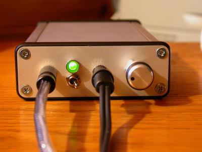
but this is my favorite MINT configuration.

medium.jpg


The case is big enough to allow the use of [2] 9v's without have to "halve" the MINT board. It's my current portable rig so I run the 9's in parallel to get more run time before I have to open the case. While the tin cases look cool the simple fact is that they don't last very well. [edit] For what it's worth, I use true 9v NIMH rechargeable batteries for my power supply, but had no issues using 9v alkalines for a time either.

Hope that gives you a slightly different perspective.

Nate


Your pot looks like it is mounted in the center of the panel, (not offset). Is it mounted on the board? (And which Hammond case are you using?).
 
Jul 13, 2005 at 1:46 PM Post #18 of 23
Quote:

Originally Posted by fincherr
Your pot looks like it is mounted in the center of the panel, (not offset). Is it mounted on the board? (And which Hammond case are you using?).


It's close, but not exactly in the center because I left the pot board mounted. It's off by about an 1/8" of an inch I think, but I haven't built one of these for a few months now so I don't know for sure. Here's a pic that shows the offset a bit better.
medium.jpg


And I'm 99% sure that's a Hammond 1455J1201. It has a ton of room inside but for me was still small enough to be my portable. And it's just so much easier to deal with than the two smaller hammonds which both have a fixed top and bottom where the J12 has a removable panel.

HTH,

Nate
 
Jul 13, 2005 at 9:27 PM Post #19 of 23
It is possible to fit two 9V batteries along with a MINT amp into an Altoids tin with the pot sticking out the end. It is indeed an "L" configuration. I don't have the amp I built this way with me, but here is as best I can remember/describe it:

Halve the boards. "Mount" the amp board at a right angle to the power supply board so that the components are facing in. I think the PS board went in upside down in the back left corder of the tin, with the amp board against the back of the tin, but I could be wrong. I remember there being a couple ways to configure it. I have both jacks and the power switch at the other end. I did extend the leads going between the boards one board width, but that may have been more convenient than necessary.

Insulate everything using electrical tape, and if you use solid core wire, the stiffness of the leads will practically be enough to hold everything in place.

Good luck! If that doesn't get the idea accross, let me know and I'll hunt down a digital camera to take some pictures.

Drew Wagner
 
Jul 13, 2005 at 11:12 PM Post #21 of 23
Quote:

Originally Posted by n_maher
Call me biased
biggrin.gif
but this is my favorite MINT configuration.

medium.jpg


[snip]

Nate


Yeah, I wonder who came up with that panel layout?

tongue.gif
 
Jul 14, 2005 at 7:54 AM Post #22 of 23
you should use the AD8620. it may be more expensive, but in the long run you'll recoup that cost by saving batteries. in my mint, the OPA2134 clipped like hell at 7.5v, but i switch that out for the AD8620 and not only is the sound much better, the amp has no clipping even down to 6v.
 

Users who are viewing this thread

Back
Top