

shrimants
1000+ Head-Fier
- Joined
- Nov 8, 2006
- Posts
- 1,176
- Likes
- 81
PREAMBLE:
Skip this part unless you are interested in development reasons and such. Questions are at the very end in color.
I have 2 active devices, A5 bookshelf speakers and a 250 watt subwoofer. I am feeding them input from my Gamma 2 Full++. The gamma2 has no software volume control ability, so I have to manually control its output via youtube and such. This is a gigantic pain in the butt because every single app has a different volume curve and setting, which changes based on if i'm using headphones or the speakers+sub.
Right now I've managed to put the sub and A5's to a matched volume and now I control both through the software control of the app itself. The main problems with this:
1) no ability for ipod or other device output. There is no y-splitter configuration, so I can either not use my subwoofer with the A5's or I have to use specifically the laptop and transfer media to it in order to play through the entire system.
2) Software volume sucks and is REALLY touchy. like 2 pixels on youtube is more than enough.
3) No easily accessible control available for each. I have to get up to change the A5 volume or reach behind the sub to change is volume and then wait to adjust and see if it is the correct volume.
4) A5's are not even close to their 50% max efficient volume. Audioengine recommends using the A5's at 50%-75% volume for maximum performance, otherwise the amp has to do a bit of a balancing act. I can barely get it past 30% because the A5's want a headphone-level input instead of line-level like the gamma2 provides. Conversely, the subwoofer is at ALMOST 50% and it is accepting line level output currently.
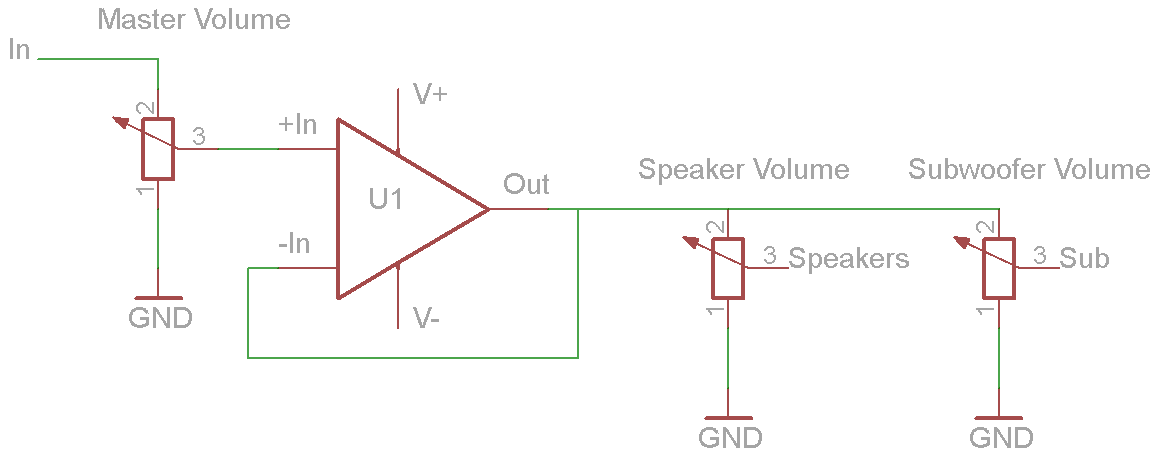
I'd like to be able to control volume in a preamp stage with a buffered y-splitter (true signal duplication, not a simple Y-splitter). I have 2 50k alps pots for the volume controls, but I dont know how to go about the signal duplicator.
Questions:
[COLOR=FF00AA]Should the preamp as an entire device present itself as a high impedance load to the Gamma 2 F++ or should it present itself as a low impedance load? I have 470uF output caps on it currently for driving headphones.
Should the preamp have a high output impedance or a low output impedance? It will be going to the subwoofer and the A5's amplifiers.
Should the potentiometers be used AS one of the gain resistors, used to attenuate the signal before the gain resistors, or used to attenuate signal after gain resistors? Should I even bother putting a unity gain buffer in this circuit or will it actually help performance to not simply have a 50K pot before the A5/subwoofer amplifier?
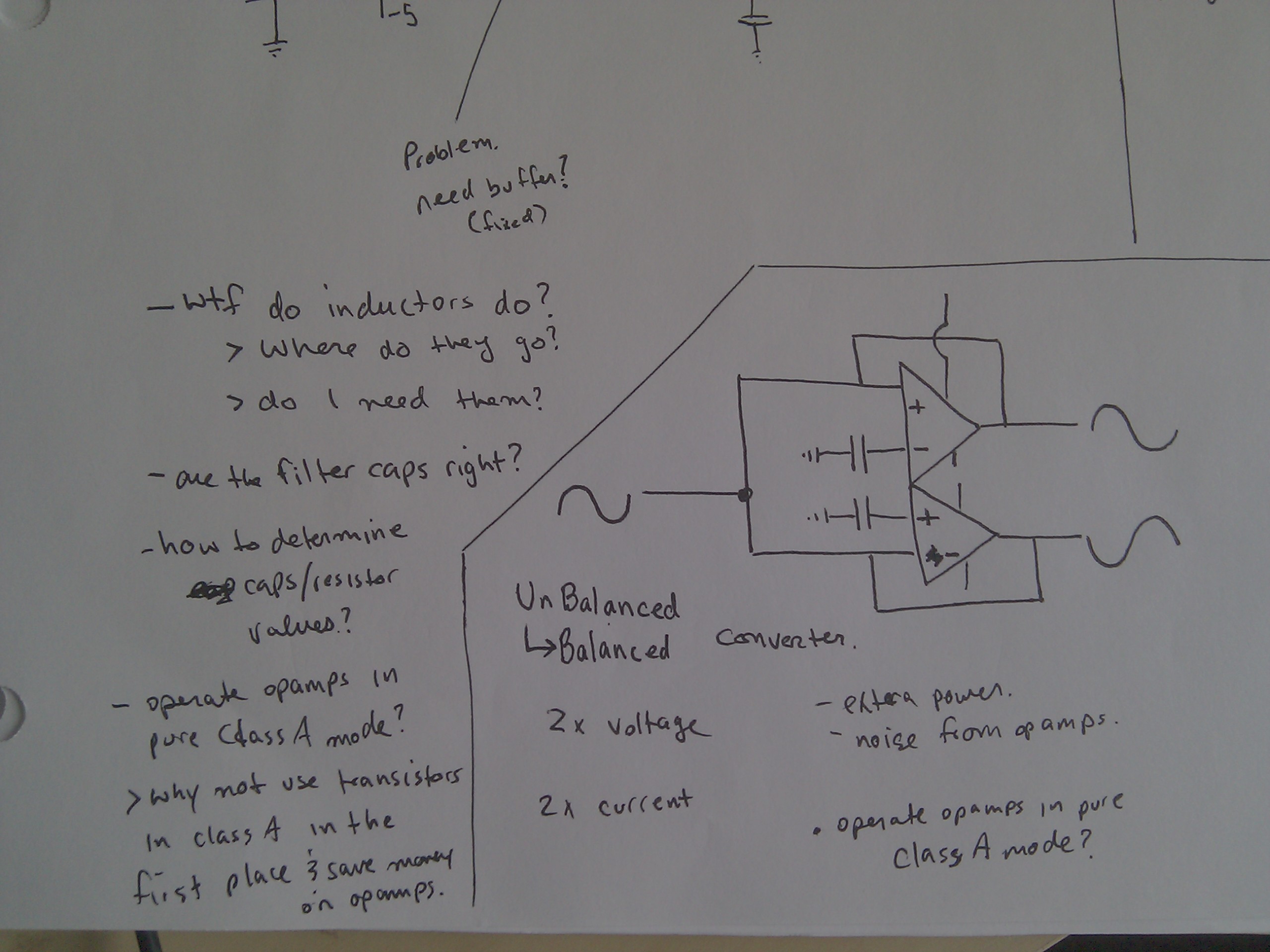
The only way I can think of to duplicate a signal is to first double the voltage (opamps or something) and then double the current (transistors). Is there a better way? Is there any way?[/COLOR] I dont want design ANSWERS, just design hints or even some baseline circuit theory knowledge if possible. I could obviously go out and buy 2 passive attenuators and simply use those but this is as much a learning and hobby experience as it is a simple necessity for me.
The old design was just the potentiometers between a bunch of RCA jacks but now i'm thinking i'll start revising and upgrading the design. First revision is a single input that splits between 2 outputs without creating a voltage/current divider situation. Second revision is buffering the potentiometers.
Skip this part unless you are interested in development reasons and such. Questions are at the very end in color.
I have 2 active devices, A5 bookshelf speakers and a 250 watt subwoofer. I am feeding them input from my Gamma 2 Full++. The gamma2 has no software volume control ability, so I have to manually control its output via youtube and such. This is a gigantic pain in the butt because every single app has a different volume curve and setting, which changes based on if i'm using headphones or the speakers+sub.
Right now I've managed to put the sub and A5's to a matched volume and now I control both through the software control of the app itself. The main problems with this:
1) no ability for ipod or other device output. There is no y-splitter configuration, so I can either not use my subwoofer with the A5's or I have to use specifically the laptop and transfer media to it in order to play through the entire system.
2) Software volume sucks and is REALLY touchy. like 2 pixels on youtube is more than enough.
3) No easily accessible control available for each. I have to get up to change the A5 volume or reach behind the sub to change is volume and then wait to adjust and see if it is the correct volume.
4) A5's are not even close to their 50% max efficient volume. Audioengine recommends using the A5's at 50%-75% volume for maximum performance, otherwise the amp has to do a bit of a balancing act. I can barely get it past 30% because the A5's want a headphone-level input instead of line-level like the gamma2 provides. Conversely, the subwoofer is at ALMOST 50% and it is accepting line level output currently.
I'd like to be able to control volume in a preamp stage with a buffered y-splitter (true signal duplication, not a simple Y-splitter). I have 2 50k alps pots for the volume controls, but I dont know how to go about the signal duplicator.
Questions:
[COLOR=FF00AA]Should the preamp as an entire device present itself as a high impedance load to the Gamma 2 F++ or should it present itself as a low impedance load? I have 470uF output caps on it currently for driving headphones.
Should the preamp have a high output impedance or a low output impedance? It will be going to the subwoofer and the A5's amplifiers.
Should the potentiometers be used AS one of the gain resistors, used to attenuate the signal before the gain resistors, or used to attenuate signal after gain resistors? Should I even bother putting a unity gain buffer in this circuit or will it actually help performance to not simply have a 50K pot before the A5/subwoofer amplifier?
The only way I can think of to duplicate a signal is to first double the voltage (opamps or something) and then double the current (transistors). Is there a better way? Is there any way?[/COLOR] I dont want design ANSWERS, just design hints or even some baseline circuit theory knowledge if possible. I could obviously go out and buy 2 passive attenuators and simply use those but this is as much a learning and hobby experience as it is a simple necessity for me.
The old design was just the potentiometers between a bunch of RCA jacks but now i'm thinking i'll start revising and upgrading the design. First revision is a single input that splits between 2 outputs without creating a voltage/current divider situation. Second revision is buffering the potentiometers.
