WaffleIron
Head-Fier
- Joined
- Aug 18, 2016
- Posts
- 68
- Likes
- 27
A preface into what this thread's aim is:
This thread will be somewhat of a build log, but will likely just initially start off with a collection of ideas and experimentation, and It'd be great to get your ideas and opinions on them. I don't have any training in pretty much anything in relation to this other than some high-school material design courses, and a few months experience with headphone modification. I expect to make some mistakes, so maybe anyone else who has the same idea won't have to. If you can see I'm getting something obviously wrong, lemme know.
-
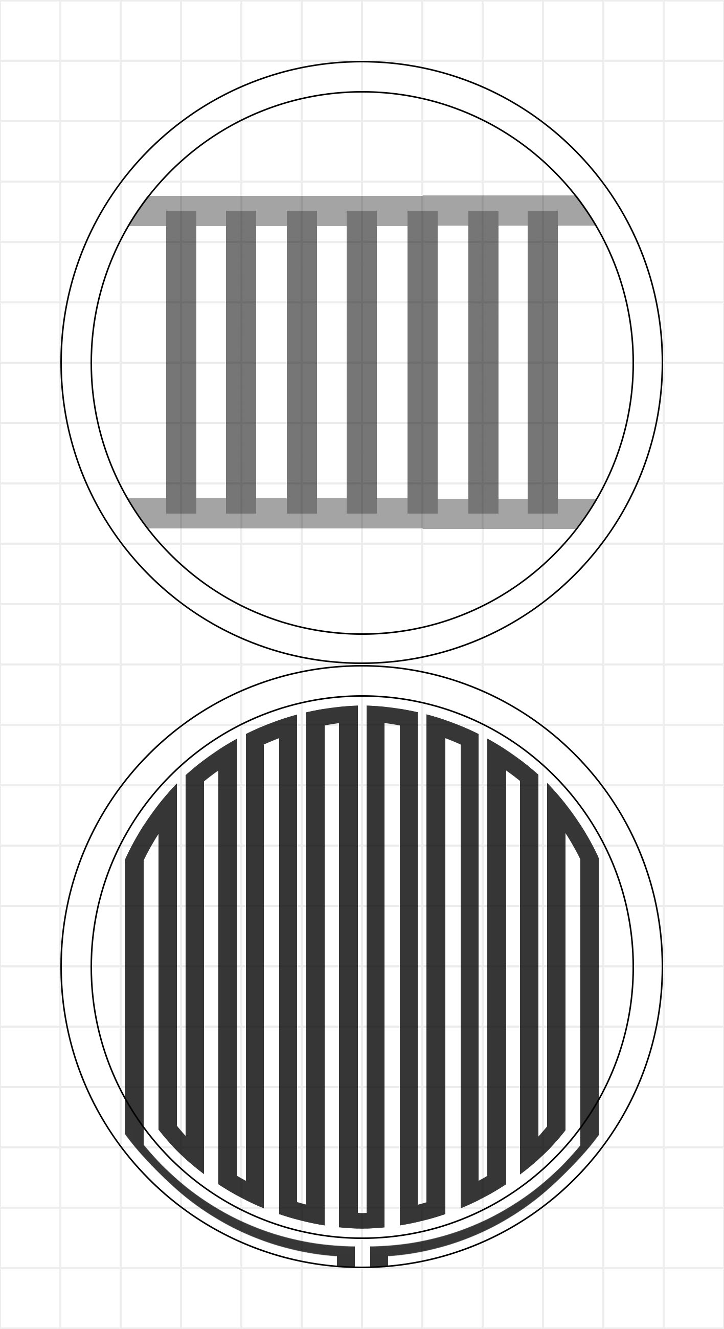
So, my main focus is the driver. Although housing and tuning is incredibly important, none of that will mean anything without the driver being functional. My thoughts are kind of being inspired by Audeze and Hifiman drivers. So far it seems I'll be using neodymium bar magnets in a striped pattern. I was originally looking into Mylar and other materials for the diaphragm, but I was then given some advice that Dupont Kapton Polymide tape is the way to go. So far I've been looking into it, and it's quite expensive to ship to Australia, but I've found a couple local retailers that look promising.
I'd stick some aluminium film to the adhesive side of the tape, and draw on a pattern for the traces, and use aluminium etching to get the trace on the diaphragm. I'n not sure if just generic kitchen aluminium foil would be the right material, or if there are more proper, thin industrial options. I'd assume the latter, but I'll probably give both a try. Ferric Chloride should be the right solvent, but actually marking the area to not be etched is the real issue. I'll either just go with a ruler and a sharpie, or create a sort of stencil out of some thick paper card. I've got tons of room for experimentation here so I'm not too worried.
Ideally, the diaphragm size would be about 100mm. Similar to Audeze drivers. Larger driver just means its easier for me to work on and conceptualize. Maybe on a second attempt I'll try and make a more portable/lightweight planar, provided the first attempt works. Might even go into more 'ear shaped' housings if I get this to work well.
At the moment, my main queries are how to attach the diaphragm to the rest of the driver. Although it won't be under significant tension, it will still be moving. Just trying to figure out the best adhesive that I don't have to re-glue every five months. The ring that I'll glue the diaphragm onto will probably be fiberglass or something similar. It needs to be rigid and flat, so fiberglass being a common PCB substrate seems like a good idea. Gimme some suggestions though if you think otherwise.
I was also given advice that tension is real important. More that I need to get it as even as possible, not actually under huge tension. I'll experiment a bit here, and probably do quite a few 'batches' of diaphragms and see which measures best, and which two are the most identical.
I'm currently working on some diagrams that I'll post here when I'm done.
This thread will be somewhat of a build log, but will likely just initially start off with a collection of ideas and experimentation, and It'd be great to get your ideas and opinions on them. I don't have any training in pretty much anything in relation to this other than some high-school material design courses, and a few months experience with headphone modification. I expect to make some mistakes, so maybe anyone else who has the same idea won't have to. If you can see I'm getting something obviously wrong, lemme know.
-
So, my main focus is the driver. Although housing and tuning is incredibly important, none of that will mean anything without the driver being functional. My thoughts are kind of being inspired by Audeze and Hifiman drivers. So far it seems I'll be using neodymium bar magnets in a striped pattern. I was originally looking into Mylar and other materials for the diaphragm, but I was then given some advice that Dupont Kapton Polymide tape is the way to go. So far I've been looking into it, and it's quite expensive to ship to Australia, but I've found a couple local retailers that look promising.
I'd stick some aluminium film to the adhesive side of the tape, and draw on a pattern for the traces, and use aluminium etching to get the trace on the diaphragm. I'n not sure if just generic kitchen aluminium foil would be the right material, or if there are more proper, thin industrial options. I'd assume the latter, but I'll probably give both a try. Ferric Chloride should be the right solvent, but actually marking the area to not be etched is the real issue. I'll either just go with a ruler and a sharpie, or create a sort of stencil out of some thick paper card. I've got tons of room for experimentation here so I'm not too worried.
Ideally, the diaphragm size would be about 100mm. Similar to Audeze drivers. Larger driver just means its easier for me to work on and conceptualize. Maybe on a second attempt I'll try and make a more portable/lightweight planar, provided the first attempt works. Might even go into more 'ear shaped' housings if I get this to work well.
At the moment, my main queries are how to attach the diaphragm to the rest of the driver. Although it won't be under significant tension, it will still be moving. Just trying to figure out the best adhesive that I don't have to re-glue every five months. The ring that I'll glue the diaphragm onto will probably be fiberglass or something similar. It needs to be rigid and flat, so fiberglass being a common PCB substrate seems like a good idea. Gimme some suggestions though if you think otherwise.
I was also given advice that tension is real important. More that I need to get it as even as possible, not actually under huge tension. I'll experiment a bit here, and probably do quite a few 'batches' of diaphragms and see which measures best, and which two are the most identical.
I'm currently working on some diagrams that I'll post here when I'm done.
