Buffer Info
Jul 1, 2009 at 4:48 PM Thread Starter Post #1 of 12

Troy81

New Head-Fier
Joined
Jul 1, 2009
Posts
27
Likes
0
First off, hello everyone, ive recently gotten into building amplifiers. ive been looking at various schematics, most amplifiers i see have a buffer in the power supply and not in the output side. i found one amplifier that seems to have no buffer at all, that begs the question, what exactly does a buffer do? ive searched long and far and i cant seem to figure it out. does anyone know what exactly a buffer does? before i start bulding amps i want to get an understanding of how all the parts work first so i can avoid overlooking important things

Is a Buffer basically a Transistor? they seem to do about the same job. if this is the the case why does a buffer (BUF634T) have 5 legs and most transistors(MOSFET) have only 3 legs?

as far as a potentimeter goes, i wanted to make sure i have an understanding. does it pretty much act as a group of different resistors that you can switch to change the gain of the amplifier?

how do you know what size resistors to use to make virtual grounds? where else do you use resistors in an amplifier circuit and how do you know what size to use?
 
Jul 1, 2009 at 8:12 PM Post #2 of 12
A buffer puts out the same voltage as it takes in (within a few percent, anyway) but with high current output. This is useful if the voltage source is capable of less output current than the buffer. This is where the name comes from: a buffer is an intermediary that prevents one thing (the load -- headphones -- in this case) from causing poor performance in another (the voltage amplifier).

Put another way, in an amp like the PIMETA, the op-amps perform voltage amplification, and the buffers do current amplification. There are very few op-amps good at both tasks.
 
Jul 1, 2009 at 11:02 PM Post #4 of 12
ok, so a buffer gives more amperage to a circuit(keeping a steady amperage) while op amps give more voltage. thus making a steady, higher voltage circuit. with the addition of capacitors to keep the voltage of the power supply steady, do i have this right?
thank you for all your help i hope im understanding correctly.

ok, another question. potentimeter, is it basically like putting a couple different resistors that you can switch between to change the gain of the amp? thats what i have understood from reading.

not to ask too many questions but i dont really understand why resistors are put where they are
ex. http://tangentsoft.net/audio/cmoy-tu...angent-sch.pdf

why are the 4.7k resistors put in there? the only logical reason i can find is maybe to keep the electricity flowing to the caps

how do you decide what resistors to put where? and why have one that just goes to the ground?

its great to have someone to help me out, there isnt anyone around here that i know that can help me out
 
Jul 2, 2009 at 4:09 AM Post #7 of 12
First, please don't modify your original post to change or add questions. It makes the thread hard to follow. If you have new questions, just post a new message.

To answer your questions:

Quote:

Is a Buffer basically a Transistor?


It could be as simple as a transistor (or JFET, or MOSFET, or tube) along with a few supporting passive parts, or it could be very complex. Single-device buffers are simple but have some limitations. More complex designs are done to overcome those disadvantages.

Quote:

as far as a potentimeter goes, i wanted to make sure i have an understanding. does it pretty much act as a group of different resistors that you can switch to change the gain of the amplifier?


If you're referring to the volume control potentiometer that's typically connected to the input of an amp, it works as an adjustable voltage divider, which is an attenuator (google these terms and you'll find plenty of descriptions of what it is). It does not change the gain of the amp, although the overall effect is similar to a gain control.

Quote:

how do you know what size resistors to use to make virtual grounds?


If you're referring to the cmoy-style voltage divider virtual ground, the resistor values should be chosen to provide the best compromise between these two factors:
1. The value should be high enough not to cause excessive current draw, which reduces battery run time.
2. The value should be low enough not to cause noise (google "resistor noise"; certain types of resistor noise is proportional to the resistance). The value should also be low enough so that the (small) amount of bias current flowing from/into the opamp through the virtual ground does not cause significant voltage drop on those resistors, which could make the ground split uneven.

Quote:

where else do you use resistors in an amplifier circuit and how do you know what size to use?

Sorry, but this question is too broad to answer. You need some basic knowledge of circuit function, in which case you wouldn't be asking this question. I know it sounds like a catch-22, but if you're really interested in learning, start by reading some introductory books on electronics.
 
Jul 2, 2009 at 9:15 AM Post #9 of 12
to understand the buffer even better, take 10 minutes to read the wikipedia about output impedance/inner resistance/voltage divider. This will provide some of the basics. The voltage amplification stage has a rather high output impedance, but the buffer "transforms" it into a lower one.
 
Jul 5, 2009 at 1:34 PM Post #11 of 12
gnd-channel.png

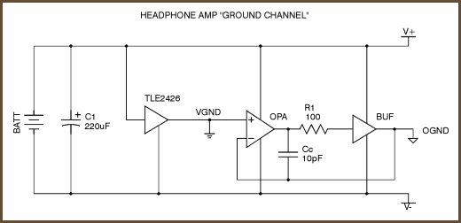
Can i only use TLE2426 n OPA2227 as Schematic above? remove the BUFF. Output ground will be directly connect after R1 and (-) of op chip will connected direct to R1 as well. Will this work?
 
Jul 5, 2009 at 2:09 PM Post #12 of 12
gnd-channel.png

this is a virtual ground for CMOY. Wondering can i remove the buffer in this schematic and connect the ground output straight to R1? OPA2227 will be used as OPA, (-) for the OPA will connect straight to R1 as well. Will this work?
 

Users who are viewing this thread

Back
Top