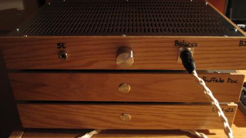
Balanced B22 and buffalo dac build
Oct 15, 2012 at 8:35 PM Thread Starter Post #1 of 26

oomi25

New Head-Fier
Joined
Apr 4, 2012
Posts
21
Likes
11
Hi guys,
I finished my new amplifier and dac recently and I don't think I can be happier. It took me about a month to build since I had alot of time to spend on that project. I didn't had alot of experience with electronics before I started, so I spend alot of time to do some research to be perfectly prepared. Even if I had experience with a soldering iron, that was a huge step for me.  Only thing I did wrong was shorting a board with my multimeter probes and I had to replace a transistor and two mosfets. Everything else went as expected. As you can see, I pretty much did the case by myself and imo, it looks very very good. The aluminum panel I ordered for par-metal didn't arrived the color I expected (It was gold like the bottom of the case) so I had to sand and polish the top panels. All 3 chassis are rock solid. I did use Neotech 18awg Up-occ copper wire for power, Double Helix 24awg occ copper for signal and Moon audio black dragon for output. The gain on the amp is set to 5x so 10x balance. Soundwise, I'm amazed how well it sound. My LCD-2 r2 are finally playing at there full potential. I was using an Audio GD NFB-10 SE before and my headphones sounded a bit dark but now, they sound just right to me. I still have alot to discover in the sound since I finished the amp yesterday but as far as I can say, every aspect of the sound is an upgrade vs my previous NFB-10. I really enjoyed doing this project and I can only recommend this to anyone who think about a DIY project like this. Sorry for my poor english, it's not my first langage.


Oct 15, 2012 at 9:36 PM Post #2 of 26
Wow! Great job! It looks fantastic, both the casework and the board assemblies. The wooden enclosures looks very good. I like how you can see all the power LEDs from the boards trough the top cover. It gives it a nice character.
 
If you'll allow me, there's two things I noticed:
 
The flat head screws on the metal panels just look like you used what you had left. It looks weird. Any plans to change them? Round head would look better, in my opinion. Same goes for the square screw in the XLR connectors. It just seems out of place for some reason. Maybe you could get some fancy screws to replace them.
 
Cable management. It is good measure to twist cables together, when they carry opposite signals. That's the whole idea behind balanced operations, after all. Your headphone's cable is braided, so why not the cable from the plug to the boards too?
 
But yeah I'm just nitpicking here. I wish I could build enclosures that looked that good. 
beerchug.gif

 
Oct 15, 2012 at 10:51 PM Post #3 of 26
Thanks alot. I really appreciate. I was planning on changing the top panels screws (I wanted to hear that thing as fast as possible). Changing screws is fairly a simple task, but I should get them first. 
wink_face.gif
 Feel free to give me more suggestions.
 
Oct 16, 2012 at 1:39 AM Post #4 of 26
agreed, looks good but for a few nit picks. I like flush mount or socket head hex fasteners, but thats just visual. the wiring on the other hand is a real concern. untwisted power and signal wires both attract and radiate noise (particularly the high frequency lines, but also your transformer wires, which are quite long), as well as being much more inductive. without being twisted (forget braided) the common mode error is not equal, thus not rejected as well. I love neotech in PTFE, use it heaps, but using 18awg solid untwisted, unshielded copper for spdif? useless i'm afraid, perhaps this technique is something you picked up from inside your last dac? i've seen it on his stuff before, its a complete no-no.

ambitious project for a first, well done! I bet you are already looking at dac upgrades, thats a pretty minimal BIII and I DONT mean that as an insult, some of the BIII builds i've seen are atrocious sprawling RF radiating birdsnests. any plans for USB? youve got enough room for Ians i2s fifo buffer/reclocker in that case
 
Oct 16, 2012 at 9:11 AM Post #5 of 26
Thank you for the observations on the cables. I'll twist all my cables and shorten the transformer wires as soon as I can. Didn't tought it was such a big deal. Never thought about adding a buffer/reclocker to the dac, I guess I'll do some research. For usb i'm waiting on twisted pear to release a usb input board that support 24/192 because the one that they have now only support 16/48. Supposed to be by the end of the year. I did keep the dac fairly simple because it was my first build and for now I didn't really need any other kind of inputs and outputs. Cool thing about DYI is that you can always upgrade. 
o2smile.gif

 
Oct 17, 2012 at 1:51 PM Post #6 of 26
Here's a little update. I did a bit of work on the wires today.
Amp: signals and outputs wires have been twisted
Dac: spdif input was changed for black dragon cable, wires from transformers have been shorten and twisted, power wires have been twisted (still have the wires for xlr out to change)
Psu: power wires have been twisted and wires from transformers have been shorten and twisted
Hope it is alot better like this.
Have any suggestions on a good usb input board that support 24/196? Or I can just wait for twisted pear to release it.


Oct 17, 2012 at 3:28 PM Post #7 of 26
Awesome build! I'm thinking about doing something like this in the future. Maybe not the wooden chassis though...I'd go for a wooden cover and a brushed aluminum faceplate instead
beerchug.gif

 
Oct 17, 2012 at 10:41 PM Post #8 of 26
For USB I use one of these - http://luckit.biz/new/product/waveio/ I've also been interested in the (very recently updated) hiface board from acko at the bottom of this page - https://sites.google.com/site/ackodac/
 
 
I would recommend looking through photos of other diy dac hookups for wiring, it's still a bit on the messy side, which, if this is all the problems you've got, means you're on the right track :wink:. It won't stop it functioning by any means, it's just one of those things that we try to do to minimise extra noise being picked up in the system. I also try to keep places where signals cross power wires as close to 90deg as possible to minimise the area where noise will be picked up.
 
 
I'd also look for a way to cover the terminal strips or solder those wires together and cover. The ones with mains voltages going through them and exposed are a bit of a risk for getting bumped if you're working inside the enclosure changing something while it's powered on. Low likelihood of it happening, but still a good precaution to have in place for your own safety.
 
Oct 17, 2012 at 10:57 PM Post #9 of 26
sorry I wasnt clear, still needs work. each transformer primary winding and secondary winding needs to be twisted individually, not just the whole bundle, which wont help at all. Other than that, the most important ones are the DC wiring, as it is even the purest copper in the world wont help, in fact here its creating problems unless you can twist it properly somehow, otherwise its very inductive and picks up noise. each power and its ground need to be twisted, particularly the DC wiring connecting to the dac and IV. Is there any way you can avoid having that AC going from one side to the other like that in the PSU?

I wouldnt wait for the TP USB, people have been waiting for that for years and besides there are better options available right now IMO.

myself I would use copper ring terminals on that terminal strip
 
Oct 18, 2012 at 12:26 AM Post #10 of 26
Quote:
sorry I wasnt clear, still needs work. each transformer primary winding and secondary winding needs to be twisted individually, not just the whole bundle, which wont help at all. Other than that, the most important ones are the DC wiring, as it is even the purest copper in the world wont help, in fact here its creating problems unless you can twist it properly somehow, otherwise its very inductive and picks up noise. each power and its ground need to be twisted, particularly the DC wiring connecting to the dac and IV. Is there any way you can avoid having that AC going from one side to the other like that in the PSU?

I wouldnt wait for the TP USB, people have been waiting for that for years and besides there are better options available right now IMO.

myself I would use copper ring terminals on that terminal strip

here's how I do it:


There, fixed that for you. =P
 
The AMB galleries are also a good source to see how, and which, wires are twisted together inside an amplifier.
 
Oct 18, 2012 at 4:39 AM Post #11 of 26
haha cheeky person, nah thats a pretty good illustration of how NOT to do layout for a final build, being literally a breadboard layout (proprietary slab of cheap plywood) for messing with different clocking schemes and listening to the result directly to a small headphone amp (the wire bal-bal) connected as a buffered balanced IV stage with my HD600. at least the pairs are all twisted lol so yes thats what I mean on that front (except the bipolar supply, which funnily enough is 18awg neotech solid core) transformer secondaries are all untrimmed too in that pic, gotta love zip-ties.

I use that headamp in my portable and I use a different IV/s at home, also slightly different power supply and a USB->i2s/DSD which isnt pictured. even thats temporary, as i'm putting 4 channels in a larger case to run my speaker crossover.

do as I say, not as I do :p
 
Oct 18, 2012 at 8:23 PM Post #12 of 26
biggrin.gif

 
Actually I posted the image as a "picture worth a thousand words" to describe how wires should be twisted together. It also clearly shows which pairs should be twisted together. I think you did a good job on that end. I didn't really take attention to the layout itself, as I thought that was irrelevant here. The OP's layout seems pretty solid.
 
Concerning the bipolar supply, would you recommend twisting these together? If yes, how? I've seen people using 3 wires together [B+ B- and Gnd], and others using two grounds in two different twists [B+ and Gnd], [B- and Gnd]. I can't make up my mind as to which configuration makes more sens.
 
Oct 18, 2012 at 9:31 PM Post #13 of 26
ps to amp wiring depends on whether the amp output is bridged/balanced vs single ended
 
with a 4-channel bridged output there is little gnd current and just twisting +/- gives fine results - although with Class A the bridged ps currents actually don't vary much either so you are really only canceling some DC mag field radiation
 
but the gnd wire still shouldn't form a big loop with the twisted ps wires - twisting all 3 won't hurt
 
for single ended amps the +/- ps wire current sum is flowing in the gnd return - so twisting all 3 is more critical


the line, xfmr wires all always have big ps rectifier/Cap charging pulses - their mag field radiation can cause hum/buzz all of the time
 
for AC pwr from the pwr entry module to the switch a common centroid wire design with star quad would possibly radiate less - I'd use smaller wire, tighter twist - the smaller wires can be closer together, have less radiating area - remember the pri line current is reduced by the turns ratio so this wire can be smaller than the secondary to ps board wire gage
 
Oct 19, 2012 at 1:24 AM Post #14 of 26
:D

Actually I posted the image as a "picture worth a thousand words" to describe how wires should be twisted together. It also clearly shows which pairs should be twisted together. I think you did a good job on that end. I didn't really take attention to the layout itself, as I thought that was irrelevant here. The OP's layout seems pretty solid.

Concerning the bipolar supply, would you recommend twisting these together? If yes, how? I've seen people using 3 wires together [B+ B- and Gnd], and others using two grounds in two different twists [B+ and Gnd], [B- and Gnd]. I can't make up my mind as to which configuration makes more sens.


yeah its all good either way, its not that bad, but its not that neat either. all of the AC is over on one side and doesnt cross over any DC or signal wiring and signal connections, as well as final DC supply connections are all very short but theres a LOT of modules there, not easy to keep neat. I need custom made mounting fittings and case etc to make a dac like this work, as I dont necessarily believe that its always a good idea to have the power supply in a separate box.

as for bipolar supplies, pretty much what jcx said, I didnt twist those ones simply because

A. I was being lazy
B. its thick solid core and not a final layout, reusing and getting all the kinks out of neotech is a pita, so I just left it straight. I had the ring terms soldered on to some scraps from another breadboard so just reused them

if you look closely at the outputs to the IV/Headamp from the dac, I have just twisted the +/- together and run the ground along beside it. you can twist all 3 if you want, but there is better common mode noise/error rejection when you twist the +/- together symmetrically. plus in a fully balanced amp like that, the signal/current path doesnt really pass ground except through the power supply
 

Users who are viewing this thread

Back
Top