B22 broken?
Sep 15, 2009 at 7:51 PM Thread Starter Post #1 of 61

oneplustwo

Member of the Trade
Joined
Jan 27, 2009
Posts
558
Likes
10
Hey folks,

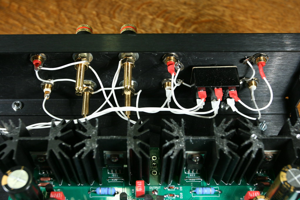
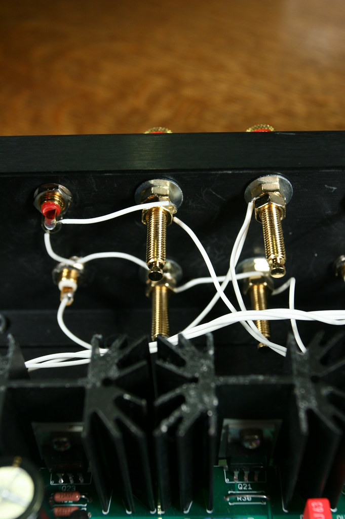
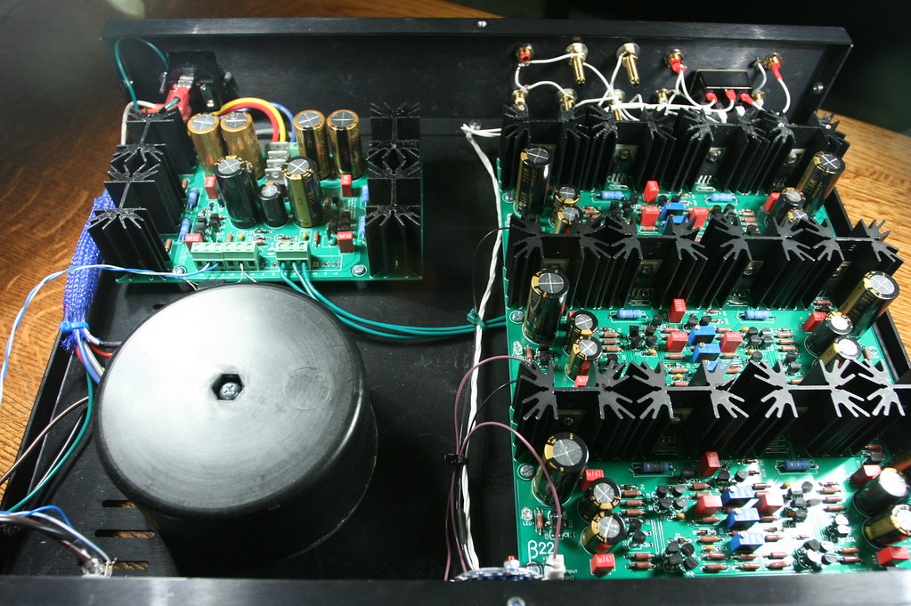
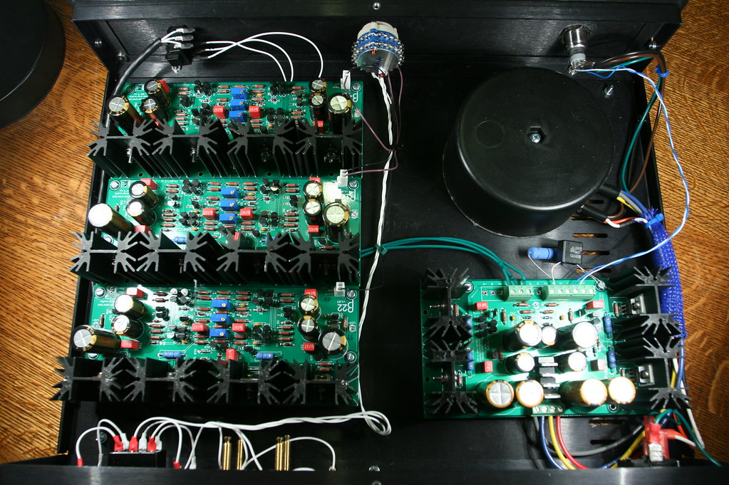
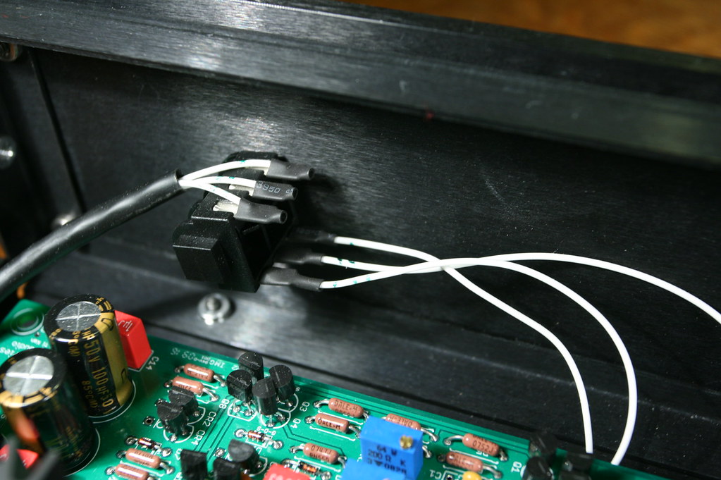
So I built a B22 with a switched neutrik headphone jack. The idea was for the signal to go "through" the jack when headphones weren't plugged in to feed a pair of speaker jacks and RCA jacks.

Everything worked fine with the headphones by themselves but when speakers were plugged in, nothing happened. Tried it with the headphones plugged in as well, also nothing. No smoke or popping heard, but now, it doesn't work with just the headphones plugged in by themselves either.

I should note that I forgot to install the zobel network across the speaker posts.

Any thoughts about what could be wrong? Could the missing zobel network have broken something or is that just a minor issue that needs to be corrected at some point?
 
Sep 15, 2009 at 8:06 PM Post #2 of 61
First thought is a cold solder joint.
What's the part number of the Neutrik jack, or a link to it?
Did you sketch out how you would wire it, and if so could you show a pic of your diagram?
 
Sep 15, 2009 at 8:36 PM Post #3 of 61
A few quick things to check:

1. Check the fuse
2. Check power supply rail voltages
3. Check for shorts from signal to ground

A picture or more detailed description of your setup would be helpful.
 
Sep 15, 2009 at 8:50 PM Post #4 of 61
I think it's unlikely this will be able to be answered without pictures. I've built multiple amps the same way, all of which are still working fine (both 3ch and 2ch beta22s) so the concept is fine, something just wasn't wired right from the get go and now something else has gone wrong. The missing zobel won't be the reason unless hooking up the speakers somehow fried the amp in which case I'm still guessing the zobel wouldn't have helped.
 
Sep 16, 2009 at 1:18 AM Post #5 of 61
maybe a short to ground as you inserted or removed the plug (while audio was playing)?

I fried more than my share of mosfets before I started making a concious effort to turn the sound off (mute it) before making 'topology changes'
wink.gif
 
Sep 16, 2009 at 4:39 AM Post #6 of 61
The B22 in question is actually mine, which oneplustwo has graciously built for me. It worked with headphones, but when I switched to speakers, I got no sound, and now no longer get sound when headphones are plugged in. Speakers and headphones were connected, and I switched by turning the volume all the way down, unplugging the headphones, then turning the volume back up.

Very quiet (but distorted) sound can be faintly heard through headphones when the volume is turned up to 75% or so. When turned on, the LED on each board does light up.

I have no experience with DIY, so just let me know what you need to see and I'll snap a pic.

Thanks for the help!

This image is the wiring on the rear of the amp. From left to right: RCA line-out, right speaker posts, left speaker posts, RCA in 1, switch, RCA in 2.

3924508903_ff78b4450d_b.jpg


Closer view of speaker post wiring.

3925295316_3a1e410ac1_b.jpg


Layout facing rear.

3925295758_dca11399b3_b.jpg


Layout facing front.

3924509127_2cd982dec0_b.jpg


Headphone jack.

3925295502_8655209918_b.jpg
 
Sep 16, 2009 at 5:26 AM Post #8 of 61
After about 10 minutes, the β22 heatsinks are definitely cooler than the σ22's. The β22 heatsinks are also not uniformly warm, the rear most board being noticeably warmest of the 3. These highly scientific readings were not perfomed with a temperature probe, but with my finger..
 
Sep 16, 2009 at 6:01 AM Post #9 of 61
Tonsosnot - thanks for putting up the pics.

Just to clarify the wiring, the outputs from the boards goes like this:

R board to headphone jack to R speaker post to R RCA jack
L board to headphone jack to L speaker post to L RCA jack
GND board to headphone jack to R GND speaker post to L GND speaker post to both R RCA jack GND and L RCA jack GND.

Also, if it helps, the amp ran for about 6 hours with headphones before I shipped it out.
 
Sep 16, 2009 at 1:22 PM Post #10 of 61
Quote:

Originally Posted by tonsosnot /img/forum/go_quote.gif
After about 10 minutes, the β22 heatsinks are definitely cooler than the σ22's. The β22 heatsinks are also not uniformly warm, the rear most board being noticeably warmest of the 3. These highly scientific readings were not perfomed with a temperature probe, but with my finger..


tonsosnot, confirm correct voltage from the Sigma, do you have access to a DDM? Are all 4 heatsinks on each board get warm, some will be hotter than others this is normal - but an outright cold one spells the death of a mosfet.
Are there any loose or partially joined wiring, turn the amp off, disconnect power cord from the IEC socket. Inspect all wiring around the pot and input/output terminals - give a little tug to ensure there is strong contact between cable and join.

oneplustwo, can you elaborate with details regarding the type of switch between speaker and headphone, any data sheets available?
 
Sep 16, 2009 at 2:24 PM Post #11 of 61
Quote:

Originally Posted by johnwmclean /img/forum/go_quote.gif
oneplustwo, can you elaborate with details regarding the type of switch between speaker and headphone, any data sheets available?


It looks to just be a simple switching headphone jack like this.

When the TRS plug is inserted, the contacts are lifted. On removal, the contacts drop and switch to a second set of pins.
 
Sep 16, 2009 at 3:00 PM Post #12 of 61
One problem that I think I see is that it does not appear that the input RCAs are isolated from the chassis, as they should be according to amb's wiring diagrams. It also does not appear as if the binding posts are isolated, that could be a very bad thing indeed as it would short the output to ground and cause very bad things.

tonsosnot - please take a picture of Q23 on both the L and R boards, I fear I know what we'll see.
 
Sep 16, 2009 at 3:35 PM Post #14 of 61
Quote:

Originally Posted by digger945 /img/forum/go_quote.gif
Why does the signal go from RCA on the left to binding post on the right in the second pic?


My assumption is that those RCAs are intended to be preamp outputs.
 

Users who are viewing this thread

Back
Top