Arduino based passive analogue input selection & volume control
Sep 26, 2009 at 7:51 AM Post #61 of 123
linuxworks;6038724 said:
nice work, atari.

Quote:

Originally Posted by linuxworks /img/forum/go_quote.gif
I see you allow for onboard power supply, for 5v. do you need to allow for a heatsink, maybe?

[…]

similarly, maybe a 5v passthru jack, so that if this board IS the 5v supply 'for the box' then maybe some other circuit needs 5v and can get it from this board?


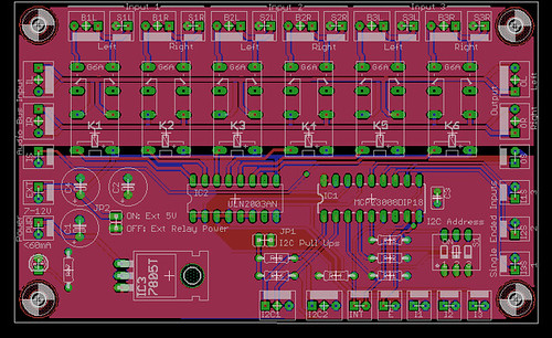
Yes, it is thought to be run from something like 7.5V. The onboard regulator will make it independent from all other digital circuits.
A bypass jumper is a nice idea. Will be added.
I don't know if the 7805 is the regulator of choice. But it will be an hardware compatible (same package, same pinout) fixed voltage regulator.
Powerwise we are dealing with less than 60mA. (40mA for two active relays, some mA for the chips, some mA wasted and some mA for safety margin).
The final board will most probably have a fair amount of copper around the regulator as basic heat sink and enough space for a small heat sink – even though I do not think that you need it. The regulator will be flat, so that the relays are the highest parts (perhaps I have to rearrange the capacitors for that - more research needed.

Quote:

Originally Posted by linuxworks /img/forum/go_quote.gif
I like s1, letting you pick the i2c address of the board
wink.gif


If you want to have ore than one board in your final preamp or other boards using the same chip - it is a must. And never throw away flexibility without a cause
wink.gif


Quote:

Originally Posted by linuxworks /img/forum/go_quote.gif
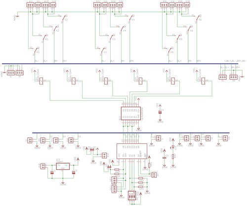
I wonder if a chip of transistor-array (uln2003 style) would get rid of all the transistors, diodes and resistors? maybe it makes the layout easier? certainly would make the build go faster and also, the chip would be socketed and if anyone blows the chip, its 10 seconds to replace it. if you blow a transistor, you have to unsolder it. so, a slight serviceability gain if you use the dip chip for relay drive.


You stick to the uln2003?
wink.gif

The transistors, diodes and resistors are dirt cheap - so no problem on this side. I will play around with your idea. Don't know yet.

Quote:

Originally Posted by DKJones96 /img/forum/go_quote.gif
Why so many audio input/output sockets? One 4 pin can take care of the balanced and a 3 pin can do single ended. That would take you from 12 sockets down to only 6 and would make the board easier to work with along with knocking a couple bucks off the build cost.


Shouldn't it be at least 5 pins? (L+,L-,R+,R-,AGND). I a single star-ground board better (simply a board with a lot of ground connections)?

Quote:

Originally Posted by DKJones96 /img/forum/go_quote.gif
I don't see volume control?


Volume and SE/BAL conversion will be different boards. Since some people will like this and that for volume or SE/BAL conversion – they would throw away the input selector if they do not like the volume control
wink.gif

Quote:

Originally Posted by linuxworks /img/forum/go_quote.gif
his board is relay selection; I don't believe its intended to do volume control.

other boards and (sub)systems are planned for that (lol).


Yes, I am a software engineer in real world too – and we like independent subsystems with standard interfaces a lot
wink.gif


Quote:

Originally Posted by DKJones96 /img/forum/go_quote.gif
I like the ULN2003 idea. It does get rid of a lot on there. Those have built in diodes and everything making it cheaper yet again.


Ok, ok convinced.

Quote:

Originally Posted by DKJones96 /img/forum/go_quote.gif
What voltage are the relays running?


The circuit (including the relays) is intended to run on 5V. So 5V-Relays should be used.

Final board will come at the end of next week. If I have time & you are lucky
a single ended only board too.

Thanks for your interest and feedback!
 
Sep 26, 2009 at 7:56 AM Post #62 of 123
I wonder, if the uln chip is used, can the relays be run from a 12v source (with 12v relays) while the logic is left at 5v?

I have a LOT of 12v relays from a surplus throw-away (seriously, a few boxes) and while they are not latching, they were free
wink.gif
but 12v. so if its possible to allow a 'relay voltage' diff from the logic voltage, that gives a LOT of install flexibility.
 
Sep 26, 2009 at 8:44 AM Post #63 of 123
Quote:

Originally Posted by linuxworks /img/forum/go_quote.gif
I wonder, if the uln chip is used, can the relays be run from a 12v source (with 12v relays) while the logic is left at 5v?

I have a LOT of 12v relays from a surplus throw-away (seriously, a few boxes) and while they are not latching, they were free
wink.gif
but 12v. so if its possible to allow a 'relay voltage' diff from the logic voltage, that gives a LOT of install flexibility.


Will give you that option (and yes, I think thats what ULNs are designed for – at least what I understand).

Yeehaw - more connectors!
 
Sep 26, 2009 at 4:47 PM Post #64 of 123
Yes they can be run on 12v. I used ULN2801 chips(same thing as a 2003 but it has 8 I/O instead of 7) for the steppers on my lathe which run 48v@450ma while the control board runs 5v.

Just remember that GND on the 2003 is common ground for both the relays and the control, the common freewheel(pin 9) goes to the input voltage for the relay coils, and the relays ground through the array.

You don't really need the connectorr. Just have the relays always run input voltage and put a jumper to bypass the regulator if they decide to run 5v. 2.54mm jumper holes means any header strip can be put there and standard computer jumpers can be used.

Not sure about others that put together systems like this but I try to design all mine to run either the same voltage throughout or locally regulate the oddball. The input control for my car runs the switching relays straight from the 14v input and I just regulate for the cell charger and the Arduino control. For this I'd probably run 5v throughout since I normally have to order my relays and the LCD, Arduino, volume control chips, and relays can all operate on it and 1 amp 5v cell charger wall warts are a dime a dozen.
 
Sep 26, 2009 at 5:12 PM Post #65 of 123
the only reason I mention allowing for non-5v relays is that sometimes you can find deals on those telco relays but at whatever happens to be available at the time, for voltage.

if the flexibility to allow for a relay-voltage and a cpu-voltage being possibly different isn't too hard to accomplish, then that's useful build-ability for the real-world and its worth it
wink.gif
 
Sep 26, 2009 at 5:30 PM Post #66 of 123
Sep 29, 2009 at 7:53 AM Post #67 of 123
The input selection section is mainly finished:
Schematics:

Board:


Changes to the early version:
  1. Usage of ULN2003 to drive the relays
  2. Using latching relays - since they are easily available
  3. Optimized board layout
  4. External connector for power – either 5V output or relay power (see EXT connector)

What is still open:
  1. Usage of combined headers for balanced input and output (probably not for the inputs - since they are more or less directly from the input connectors)
  2. Grounding strategy (star like vs separate grounds)
  3. The board is still a bit too big - perhaps it can be done a bit smaller
  4. avoiding open circuit problem.

So I have two questions:
Is the analog grounding OK? Or should I remove all grounds from the analog connectors and have a single ground connector for a star like grounding scheme?
How should the open circuit problem. Put some resistors to AGND in the audio bus? Switch some resistors to AGND when no input is selected?
Currently I am planning to solve this problem with the volume control.
 
Sep 29, 2009 at 2:29 PM Post #69 of 123
latching relays need both sw and hw help.

background for those that have not used these before: latching relays (single coil type) need a short pulse of current in one direction to latch them one way; then you remove the current. keeping the current won't help and only heats up the part.

to change to the other relay position, reverse + and - supply to the relay, pulse it and then remove power.

or, equiv to 'remove power' is to bias both leads at the same level. if you have a logic '1' going to one wire and a logic '0' to another, that creates a voltage diff (hopefully enough to latch) and then you can either send both 'wires' a 0 or both wires a 1. that will cause 0 voltage to flow across the coil, a good thing.

even better, some controllers can go into 'high z' state and remove themselves from the connection, entirely. in that case, you only need to 'high z' one of the wires to fully break the circuit.

hardware wise, the diodes are more tricky since its dual polarity to toggle the relay. 2 'outputs' of buffers go to the 2 relay wires and one buffer should be at opposite voltage from the other.

also, a software thing about timing: you MAY want to have control over the 2 legs of the relay and how much time is spent in writing the 1 to the first wire, keep holding it, then write a 0 to the other wire, keep it for a 'hold time' to let it latch' and then undo one of the wires (break its connection) after some more delay. all those delays should be software configurable (on a multibank relay system). on simple systems, you may not need all those timing details settable.

latched relays are a PITA to deal with, but they have memory (so that once you set them, they hold their state until told to change; even across reboots) and they also need no 'holding' power once latched. this saves a LOT on power supply heat.
 
Sep 29, 2009 at 2:50 PM Post #70 of 123
And latching relays are harder to get locally
wink.gif

What is a pitty.

As linuxworks states (very well explained – better than I could do) they are a bit trickier software wise but consume less power. Less danger of interference and so on.
 
Sep 29, 2009 at 5:20 PM Post #71 of 123
It saves a lot of power but I don't think we need to worry about that since these will likely be used with B22s and tube hybrids. Not exactly the most efficient of amplifiers.

Holding across reboots isn't going to help much unless you write the current mode to something other than ram in the MCU. Otherwise it'll have to reset all the latched relays to a programmed default when power is applied since it'll have no idea where the relays are otherwise.
 
Sep 29, 2009 at 5:41 PM Post #72 of 123
Quote:

Originally Posted by DKJones96 /img/forum/go_quote.gif
It saves a lot of power but I don't think we need to worry about that since these will likely be used with B22s and tube hybrids. Not exactly the most efficient of amplifiers


If it means you can use a PCB mount transformer, I'd say it's worth it. I doubt people will run this off the main amplifier PSU, so some sort of auxiliary transformer winding will be needed. Given some of the space constrained builds I see around here, I think it's a good idea.
 
Sep 29, 2009 at 5:44 PM Post #73 of 123
Quote:

Originally Posted by DKJones96 /img/forum/go_quote.gif
It saves a lot of power but I don't think we need to worry about that since these will likely be used with B22s and tube hybrids. Not exactly the most efficient of amplifiers.


why assume any kind of amp? this could be in a preamp box on its own.

regardless of how heat-generating the amp is, that's still not a good reason to waste heat in a relay. it makes the 5v supply need to be stronger than it should be.


Quote:

Holding across reboots isn't going to help much unless you write the current mode to something other than ram in the MCU.


huh? the mcu has eeprom and I've saved settings there before (last volume setting for the various inputs, the input last selected, power on/off status, etc.)

but regardless, the relays will hold the last setting and so when you power on again, even the cpu does not have to engage unless you want to CHANGE something.

Quote:

Otherwise it'll have to reset all the latched relays to a programmed default when power is applied since it'll have no idea where the relays are otherwise.


true that you can't sense the current position of the relays; but they won't change on their own and so the last 'management change' IS the last change status of the relays.
 
Sep 30, 2009 at 6:02 AM Post #74 of 123
Regarding the relay power:

I am a big fan of latching relays (linuxworks has explained the advantages very good). But in comparison to the fact that they are really hard to get (mouser has some) and that we are talking about 40mA of current in total (2 relays are on and each consumes 20mA) – I think it is bearable to use the less efficient relays.
 

Users who are viewing this thread

Back
Top