Arduino based passive analogue input selection & volume control
Sep 19, 2009 at 8:13 PM Post #46 of 123
I was not trying to suggest using PICs or BS's
In fact, I would very much dislike that....


I wanted to know why you don't just program the atmel AVR chips directly using GCC-avr, etc.
there is a very large atmel AVR community, and lots of documentation.

Maybe I am being ignorant. Maybe the wiring/audrino stuff is more valuable than I know.
 
Sep 19, 2009 at 8:20 PM Post #47 of 123
Quote:

Originally Posted by nullstring /img/forum/go_quote.gif
I wanted to know why you don't just program the atmel AVR chips directly using GCC-avr, etc.
there is a very large atmel AVR community, and lots of documentation.


but its still not as beginner-friendly as the arduino 'sketch' idea. a lot of grunt work is done for you in the arduino world. and a lot of user programs at the arduino level, too; so the integration aspect again enters into it.
 
Sep 19, 2009 at 8:38 PM Post #48 of 123
ok, so, basically for the sake of convenience and rapid development the arduino environment is key.
In the end, you don't really care if you spend extra money to save time, and can get that device in use quicker.

However, if your arguments hold up (I haven't done much more research than what I've read in this thread), then it seems like this project could become very popular.
Popular to the point where you might be selling PCB's with a presoldered and preprogrammed chips
In this case, I hope that you wouldn't still be using arduino =p

But, maybe the difference is less than I realize. /me shrugs


I am the type of person who prefers to understand how everything works than to use a frameworks that does everything for me. Therefore, I am going to try to use the AVR directly, but who knows how thats gonna turn out =)
 
Sep 19, 2009 at 9:49 PM Post #50 of 123
arduino is source based. cd into the library routine area, edit the file, 'touch' rebuild button in the gui and now you have user edited library code integrated.

it really is nicely abstracted and MUCH less scary than any other kind of microcontroller (imho).

one of my goals was to have the source be friendly enough that people who have zero programming background can still make some level of source-code changes, rebuild and redownload and have *their* code run. even basic stamps were not *that* easy.

there's also a bootloader that's part of the arduino env. it makes development only cost $20 (for a magic usb cable). that's it. quite a low barrier to entry. PIC programmers tend to be $35 and up (casual search). and with arduino, there is really ONE flash programmer (the magic ftdi usb cable). with PIC, they seem to need a variety (sometimes) of flashers.

PIC is perhaps a good choice for a fully commercial project. but I'm quite convinced that arduino is the right choice for this kind of market (DIY for non-controller people who want to get into controllers).
 
Sep 19, 2009 at 9:51 PM Post #51 of 123
Quote:

Originally Posted by PJPro /img/forum/go_quote.gif
Hmmmm. As a former coder (now manager) I'd be keen to pitch in and help where I can.


we had an inside joke at a previous software company I was at: our boss (who stayed away from coding) would 'threaten' us that if we were getting late on our milestones, he'd *join in* on the coding. that usually scared us enough that we'd make our milestones
wink.gif
 
Sep 20, 2009 at 8:12 AM Post #52 of 123
Quote:

Originally Posted by nullstring /img/forum/go_quote.gif
ok, so, basically for the sake of convenience and rapid development the arduino environment is key.
In the end, you don't really care if you spend extra money to save time, and can get that device in use quicker.

[...]

I am the type of person who prefers to understand how everything works than to use a frameworks that does everything for me. Therefore, I am going to try to use the AVR directly, but who knows how thats gonna turn out =)


That is exactly the point.
A lot of people on this board have never done micro controller programming before.
For them arduino is the easiest way to enter the world of microcontrollers and do not fear the complexity. Arduinos are easy and there is a lot of help out there if you get stuck.
The whole project will be mordular and standardized enough that you can use it with the platform of your choice. No matter if you want to go atmel, PIC, ARM7 or whatever.
So, the tag 'Arduino' is just to signal the beginners: 'There is no complex stuff here to fear
wink.gif


And please. Do not compare the advantages or disadvantages of different platforms here: Use what you want and if you dont have a clue try the Arduino way
wink.gif
 
Sep 20, 2009 at 10:26 AM Post #53 of 123
Quote:

Originally Posted by linuxworks /img/forum/go_quote.gif
we had an inside joke at a previous software company I was at: our boss (who stayed away from coding) would 'threaten' us that if we were getting late on our milestones, he'd *join in* on the coding. that usually scared us enough that we'd make our milestones
wink.gif


Oh.
frown.gif


So when's your 90% date?
smile.gif
 
Sep 20, 2009 at 12:50 PM Post #54 of 123
Ok,

designing the basic switching & filter section was easier than I thought.
Ok, it is just a bunch of relays. The rest of the circuit will follow:


(click for larger resolutions)

B1R/B1L, S1R, S1L is Input 1 (left, right, balanced, single ended)
B2.. is input 2
FI1L/R is the input of filter 1
FO1L/R is the output of filter 1

K1-K8 are the relay coils. Coils organized in one row will be switched on or of at the same time.

All input will be hooked on or off from the bus (the blue line). The bus contains all the balanced signals (BL+,BL-,BR+,BR-).

Between the output and the bus several filters can be switched – here we show only one filter.

I incorporated some resistors, so that all inputs, not hooked on the bus will be grounded by a 10k resistor to avoid open loop circuits. (thanks for the hint linuxworks).

The final version will include 4 inputs and 3 filters.

The filters (which all will be separate boards) could be:
- Volume control
- Single ended Balanced conversion
- Whatever

So next to the I2C driver section (the interface to the arduino).
 
Sep 20, 2009 at 1:35 PM Post #55 of 123
Quote:

Originally Posted by PJPro /img/forum/go_quote.gif
Oh.
frown.gif


So when's your 90% date?
smile.gif


actually, the source will be released so anyone can jump on it and extend or modify it.

some early snapshots of source code are here:

http://www.netstuff.org/audio/

code needs cleaning up (I've created too many ways of doing a lot of the same things) but its how things 'evolved' on their own, sort of
wink.gif
 
Sep 25, 2009 at 10:51 AM Post #56 of 123
There are updates on this project.

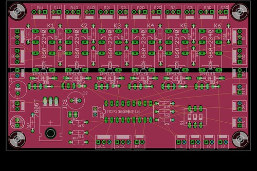
Thanks to the encouraging help of linuxworks I was able to design the first complete microcontroller oriented input selector:


This board is intended as an extension for linuxwork's LCDuino.

The features:
  1. I2C based control via MCP23008
  2. all inputs are switched by relays
  3. all inputs can be either single ended or balanced (singe ended to balanced conversion will come as a different board)
  4. several board can be combined to get more inputs

What changed regarding to the prototype:
  1. usage of non latching relays (easier to source)
  2. filter selection is gone (will be a different board)

A first draft of the board is also available. No PCB traces drawn until now. Check the thin yellow lines what goes where (click for high res versions)


The analog section is on the top part of the board. With some nice ground plane on top and bottom of the board.
The digital section is completely on the bottom part of the board. Ground plane on bottom, VCC plane on top.

What do you think?
Is there anything I have done wrong or I can do better?
What do you think?
 
Sep 25, 2009 at 2:08 PM Post #57 of 123
nice work, atari.

I see you allow for onboard power supply, for 5v. do you need to allow for a heatsink, maybe? the relays (or one of them) will be always on, so it will have constant current drain. also, for those that already have 5v inside their box, maybe provide a molex header or something where people can bypass the onboard power supply (not install those parts, either) and just run the 'box' 5v into this board?

similarly, maybe a 5v passthru jack, so that if this board IS the 5v supply 'for the box' then maybe some other circuit needs 5v and can get it from this board?

I like s1, letting you pick the i2c address of the board
wink.gif


I wonder if a chip of transistor-array (uln2003 style) would get rid of all the transistors, diodes and resistors? maybe it makes the layout easier? certainly would make the build go faster and also, the chip would be socketed and if anyone blows the chip, its 10 seconds to replace it. if you blow a transistor, you have to unsolder it. so, a slight serviceability gain if you use the dip chip for relay drive.
 
Sep 25, 2009 at 2:20 PM Post #58 of 123
Why so many audio input/output sockets? One 4 pin can take care of the balanced and a 3 pin can do single ended. That would take you from 12 sockets down to only 6 and would make the board easier to work with along with knocking a couple bucks off the build cost.

I don't see volume control?

I like the ULN2003 idea. It does get rid of a lot on there. Those have built in diodes and everything making it cheaper yet again.

What voltage are the relays running?
 

Users who are viewing this thread

Back
Top