APPJ Mini2013 Tube amp (6J1 pushing 6P1, 3w per channel)
Jan 28, 2023 at 3:41 PM Thread Starter Post #1 of 8

AudioCats

Headphoneus Supremus
Joined
Feb 25, 2007
Posts
3,726
Likes
264
Location
CO, USA
starting a thread to document some info on this little amp.

This is probably still in production as there are multiple listings on ebay. Typical price is $120 at this point.
I recently bought a used (likely a customer returned semi-defective) unit, for a bit less, mainly to play with.

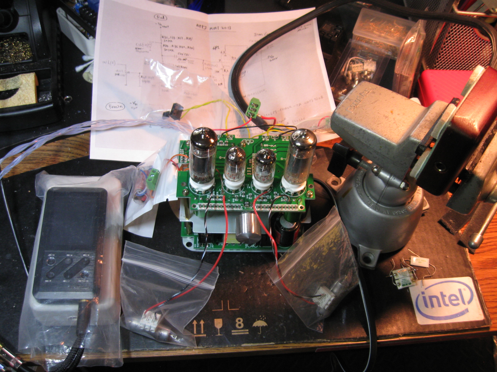
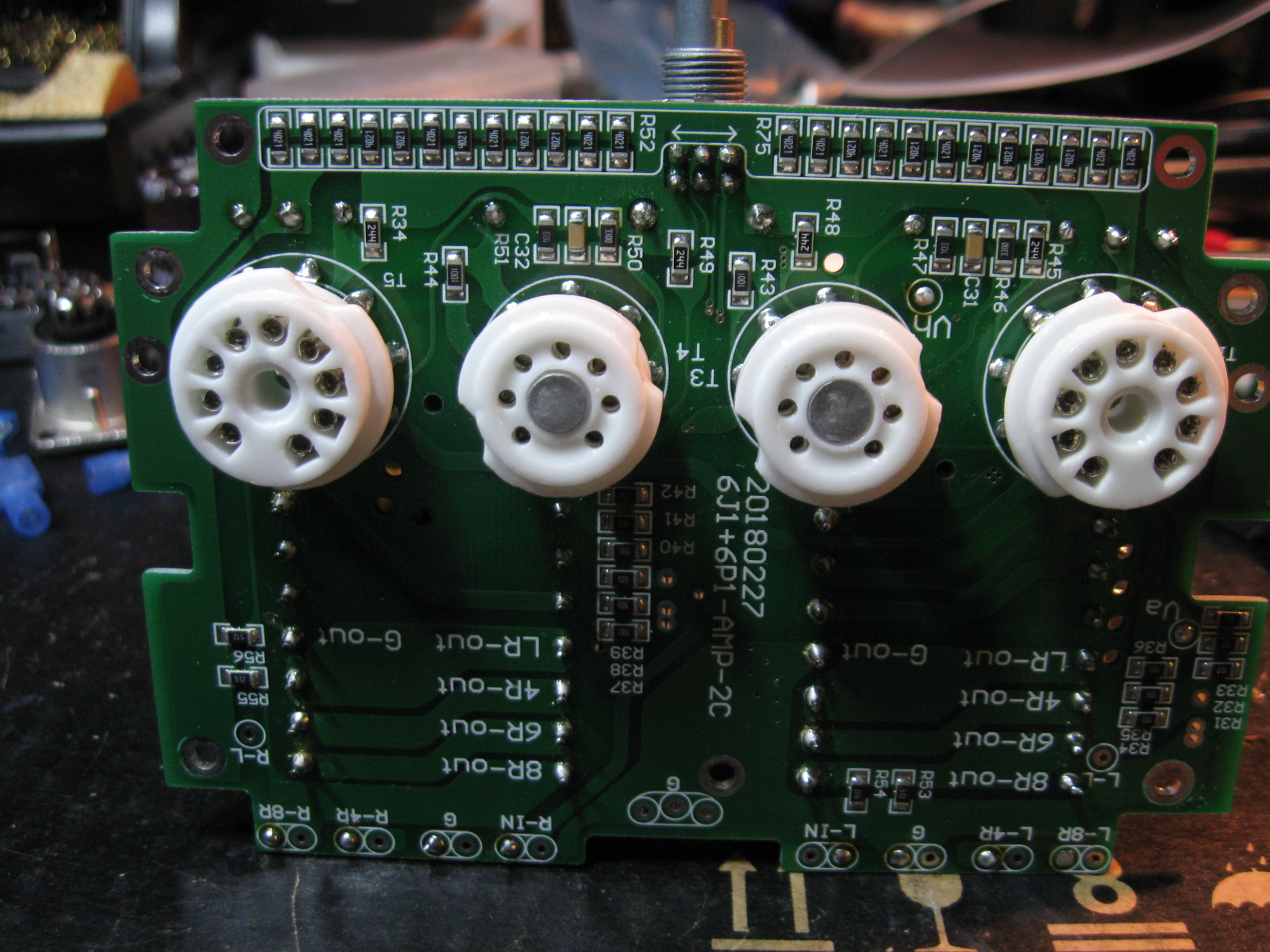
Two 6J1 pushing two 6P1, spec claims 3w per channel.
The one I got has 4 ohm and 8 ohm speaker jacks in the back, some (newer?) units appear to also have 6 ohm outputs. The 6 ohm tap is present on the PCB in my amp, they just didn't install the output hardware for it.

Disassembly: this amp has to be taken apart piece by piece, from the top
1) remove the top aluminum plate (four screws)
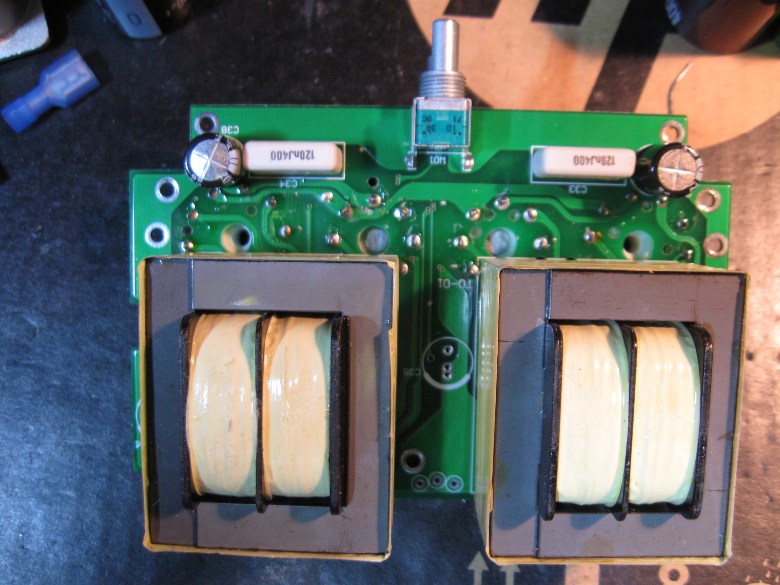
2) pull off the volume knob, and remove the nut/washer
3) remove the five screws holding the top pcb, and desolder the wires in the back and red (Va, which is HV) and brown (Vh, filament). The top PCB can then be tilted and slide out.
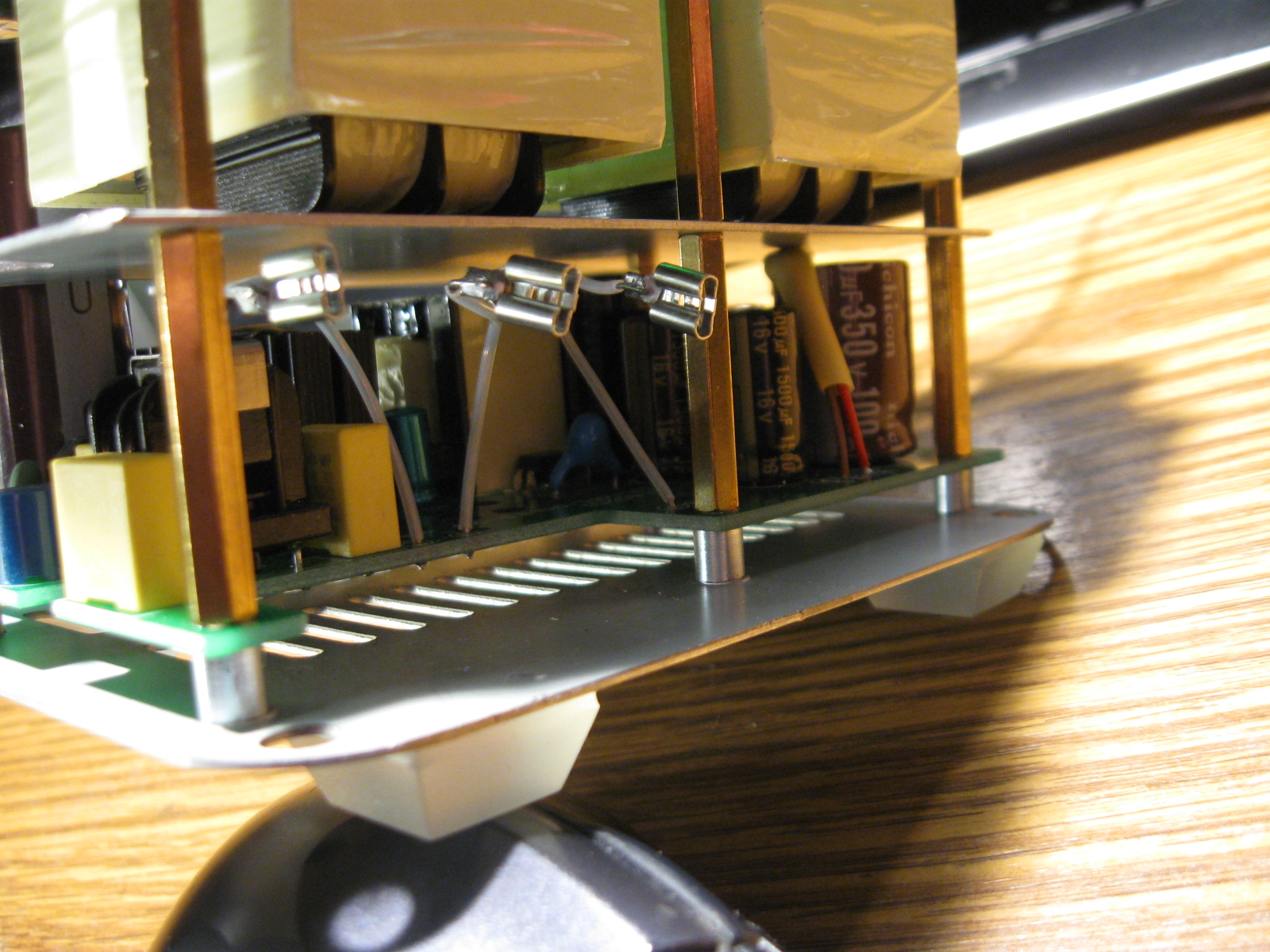
4) removed the five long brass stand-offs. Then remove the steel divider plate.
5) unplug the G, N, L wires from the power jack.
6) Remove the four larges screws from the bottom, the bottom PCB is now free.

then put the whole stack back together outside of the aluminum shell.

IMG_0941.JPG
 
Jan 28, 2023 at 4:01 PM Post #2 of 8
Power supply circuit seems to be similar to what is in my appj pa1502a, the build quality is not as good.

IMG_0946.JPG


IMG_0947.JPG


** There is no ground wire going from the bottom power supply board to the top amp board. The amp use three of the brass stand-offs to serve the ground wire function.


top (amp) PCB:

IMG_0949.JPG

IMG_0950.JPG


One of the cathode by-pass cap was installed backwards and blown, it is probably why this unit was returned.

IMG_0945.JPG


schematic can be found by googling "appj mini2013 circuit diyaudio".

The top pcb is marked
" 20180227
6J1 + 6P1 -AMP -2C",
the circuitry is mostly the same as in the DIYaudio schematic, except on this board tube filaments are wired in parallel (the Vh voltage is 6v)


Voltage measurements:
Va=260v, Vh=6v.
voltage across inter-stage coupling caps: depending on the tubes used. around 70v with stock 6J1 installed; around 50v with RCA 6AK5 installed.

No turn-on / turn-off pop.
Basically no back ground hum when used with my orthodynamic phones (T20v1, T50rp, He6se).

power consumption is 35w.
 
Last edited:
Jan 28, 2023 at 4:27 PM Post #4 of 8
upgrades so far:
a) volume control converted to shunt type, Currently using caddock TF020 film resistors as input series resistors.
b) interstage coupling cap change to film cap. Currently using 0.27uf/300v 96P VitQ.
c) cathode bypass caps of 6P1 changed to 220uf/50v Nichicon Muse ES. In order to fit the ES into the space, the input reservoir cap (very tall) in the bottom board was changed to a shorter/fatter cap.
d) added a 3uf/400v film cap to the HV rail of top board.


IMG_0951.JPG


IMG_0952.JPG


The sound is quite good pushing He6se and T50rp.

*** update, input series resistor (in shunt volume control) comparison
-- with caddock TF020: more transparent, clean with good bass. A little sterile at times, not as emotionally involving as audionote tantalum.
-- with audionote tantalum non-magnetic: thicker and creamier; more emotionally involving; not overly sweet/cheerful, sad songs are still sad, which is great.

I will keep the AN tantalum in there.
 
Last edited:
Jan 29, 2023 at 3:50 PM Post #5 of 8
potential (design related ? ) issues:

with output tubes are installed but input tubes are missing/not working:
the HV rail (Va to ground) is around 350v. Which means the 6P1 will be seeing at least 300v (anode to cathode). while 6P1 anode voltage spec is 250v.
and the reservoir caps for the HV rail are both 100uf/350v. The second reservoir (the one after the capacitance multiplier) might be ok, but the first one will definitely see peak ripple voltage higher than 350v. It might not last too long under this condition.

with only the input tubes installed, the HV floats to around 320v. The plate resistors string above 6j1 will drop some voltage but the 6j1, in this scenario, can still see higher anode/cathode voltage than the 120v max listed in the spec sheet.


with all tubes installed and operational (that is, when all tubes are working properly), HV is around 260v, 6P1 cathode voltage around 10v, even then the anode/cathode voltage is close to the 250v spec limit.

With no tube installed, the switching power supply board would not stay on ( 0 watt power draw) and the HV rail only goes up to around 250v. However, in this amp there is no bleeder resistor to drain off charge stored in HV reservoir caps. If the amp was turned on with no tube installed (which floats the HV rail to 250v), then turned off, then tubes get installed, the 6j1 will see the full 250v anode/cathode voltage (filament is not hot, no current going through plate resistor string). And this situation will sustain until the filament gets hot (amp turned on).
 
Last edited:
Jan 29, 2023 at 4:08 PM Post #6 of 8
inter-stage signal capacitors:

these capacitors block less than 100v under normal operating condition, but in the worse-case scenario they could see over 350v (see post #5 above).

VitaminQ 96P:
-- fatter bass, but not as deep and not as clean
-- smaller stage
-- some emphasis on vocal frequency, making the songs more emotionally engaging.
-- more "simple" sound, not as much micro details as the FT teflon.


Soviet FT aluminum foil/ teflon:
-- cleaner and deeper bass
-- more ambient details, more "live" when playing concert recordings.
-- even and smooth, no irritations
-- large sound stage
-- beautiful vocals but not as emotionally engaging as VitQ

I think the FT is a better choice overall, for all music types. But it is not possible to fit 600v FT3 caps into the stock aluminum enclosure.
 
Mar 12, 2024 at 10:14 AM Post #8 of 8
upgrades so far:
a) volume control converted to shunt type, Currently using caddock TF020 film resistors as input series resistors.
b) interstage coupling cap change to film cap. Currently using 0.27uf/300v 96P VitQ.
c) cathode bypass caps of 6P1 changed to 220uf/50v Nichicon Muse ES. In order to fit the ES into the space, the input reservoir cap (very tall) in the bottom board was changed to a shorter/fatter cap.
d) added a 3uf/400v film cap to the HV rail of top board.

IMG_0952.JPG
Hi AudioCats,

Could you please share the spec & height of this black "shorter/fatter" cap? I'm so noob then wanna try to replace stock caps with Nichicon Muse and that big one at least.
 

Users who are viewing this thread

Back
Top