An example: the repair of TOSHIBA XR-P21 vintage cd player.
Dec 5, 2011 at 4:07 AM Thread Starter Post #1 of 18

kaosun

Member of the Trade
Joined
Dec 27, 2010
Posts
131
Likes
33
[size=medium]One friend from Head-fi sent me a Toshiba XR-P21 for repair.[/size]
[size=medium]It’s an vintage portable cd player made around 1988, comes with a power supply base and looks cute. However, it has no response when it is plugged in and pressed play. It’s a challenge for me because the famous three models of XR series, including P20, P21, and P22, none of them is easy to handle. Therefore, I recorded the progress with cellphone to show you how a cd player is repaired.[/size]
 
[size=medium][/size]
 
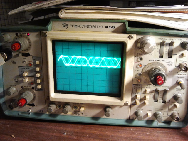
[size=medium]Inspection: when play is pressed, no response, no laser beam, no mechanical movement, no display. Rotate the turntable, it patters.[/size]
 
[size=medium][/size]
 
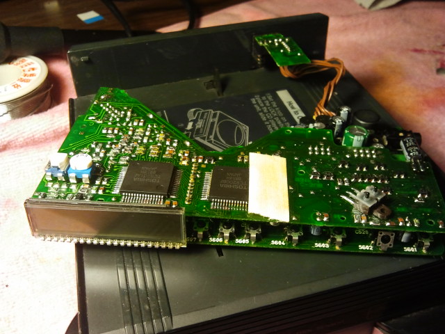
[size=medium]Open the cover, it looks intact and no evidence that it lacks anything. Maybe it just broken something.[/size]
 
[size=medium][/size]
 

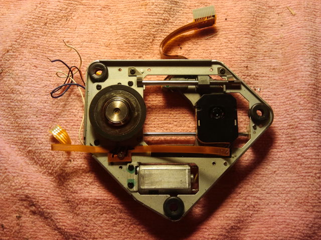
[size=medium]The whole circuit is divided into 2 boards. The upper one includes power supply, DAC/audio, and CPU/LCD. The lower one includes drivers, DSP, and RF amp.[/size]
 
[size=medium][/size]
 
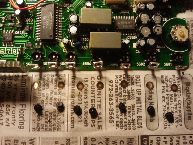
[size=medium][size=small] [size=medium]As usual, the caps of power supply must be replaced totally. It’s the area above two white sockets.[/size][/size][/size]
 
[size=medium][/size]


[size=medium][/size]
 
[size=medium][/size]
 
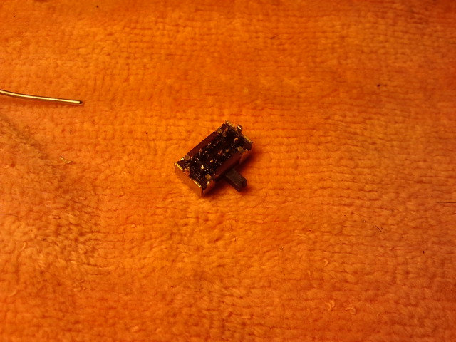
[size=medium][size=medium]After replacing all the caps and cleaning the each side of the power supply board, BTW lubricate the volume VR.[/size][/size]
[size=medium][size=medium][/size][/size]
 
 
Dec 5, 2011 at 4:32 AM Post #2 of 18
[size=medium]After testing all the buttons, most of them cannot response exactly; therefore, they will be dissembled and cleared. [/size]
 
[size=medium][/size]
 
[size=medium]As experience, the variable resistors used to determine the main parameters like TB, FB, TG , and FG are easy to get problem. For example, bad contact, resistor broken, poor lubrication. All should be replaced by brand new VRs.[/size]
 
[size=medium][/size]


[size=medium]Testing again, no response.[/size]
 
[size=medium][/size]
 
 
Check the power supply of the 54th pin of the CPU. It should be +3.8V coming from the DC-DC power supply circuit (Q803 Ba9700 core); however, 0V. The power supply of the BA9700, 0V either.
Then check the source of the BA9700, Q801 TL499. It’s another DC-DC step-up switching power generator, it raises both battery and power base voltage to BA9700 and BA9700 generates the power of CPU. Further inspection indicates that the power from the base has been sent to the Q801; however, the ground of the Q801 is disconnected from the base. The P21 controls the whole power supply by a power switcher by cutting the ground line. Unfortunately, it has been corroded inside. After repairing the switcher, it powers on.


[size=medium][/size]
 
[size=medium][/size]
 
[size=medium][/size]
 
[size=medium]It has been dissembled.[/size]
 
[size=medium][/size]
 
[size=medium]Mechanical module and laser head.[/size]
 
[size=medium][/size]
 
[size=medium][/size]
 
[size=medium]The main motor must be replaced. [size=medium]The turntable must be taken down from the original motor.[/size][/size]
[size=medium] [/size]
[size=medium][size=medium][/size][/size]
[size=medium]The model is Rf410, same with the notorious motor of SONY D303/35 only it has a longer spindle. [/size]
 
[size=medium][/size]
 
[size=medium]The spear motor is a RF410CH D/V4.0, a little different with the original D/V5.9.[/size]
[size=medium]The figure of 4.0 and 5.9 stands for the working voltage. It means when the 4.0 motor is installed into the circuit designed for 5.9 motor, it will run faster. However, the rotation speed is under control of closed loop. Because the speed of the linear velocity of the disc is precisely controlled at 1.3M/s, 210r-540r/m, the increase of the rotation will be detected and be offset by decrease the drive voltage of the main motor. So the replacement of the motor is possible. Actually, I tried replacing the RF410 D/V5.9 by another RF410 D/V2.0. Guess what? It works fine! It seems the control range of the motor is wide.[/size]
 
[size=medium]In order to extend its life, both the upper and lower bearings should be lubricated. So the hole on the bottom of the motor is drilled to add oil.[/size]
 
[size=medium][/size]
 
[size=medium]Install the turntable to the new motor; determine the height of the table by inserting name cards.[/size]
[size=medium]The height should be measured before taking it down. Because the spindle of the new motor is a little shorter than the original one, the glue is necessary to be added into the hole of the table.[/size]
 
[size=medium][/size]
 
[size=medium]Testing the original laser head.[/size]
[size=medium]Both RF waveform of the real cd and CDR are 0.4Vp_p, far less than technical requirement:[/size]
[size=medium]Real CDs: 1.2Vp_p, CDR:0.8Vp_p.[/size]
 
[size=medium][/size]
 
[size=medium]The RF waveform of reading topic of CDs.[/size]
 
[size=medium][/size]
 
[size=medium]After testing, the laser head is sentenced aging. [/size]
[size=medium]Dissemble the laser head, check and clean inside, then replace its laser diode.[/size]
 
[size=medium][/size]
 
[size=medium][/size]
 
[size=medium][/size]
 
[size=medium]Replace the original laser diode by a brand new ROHM RLD78MD. It’s a 780nm red laser diode. Because it's used in MD play/recorder, it has more laser power (10mw) than CD laser diode (5mw). It means the diode can extend its life under less working current, it will work at lighter working load.[/size]
 
[size=medium][size=medium][/size][/size]
 
[size=medium]After replacing the laser diode, the beam path changed. The precisely adjustment is necessary.[/size]
[size=medium]Readjust the photo diodes IC.[/size]
 
[size=medium][/size]


[size=medium]Amplify the surface of the photo diode IC and display it on the wall by projector by using specific microscope. The laser spot fails to locate in the middle of the PD IC.[/size]
 
[size=medium][/size]
 
[size=medium]Adjust the PD IC in order to guarantee the precise laser location, reassemble all and test.[/size]
 
[size=medium][/size]
 
[size=medium]Awesome! [/size]
[size=medium]The RF waveform of CDR reaches to 1Vp_p! Decrease the laser power immediately to 0.8Vp_p.[/size]
 
[size=medium][/size]
 
[size=medium]Recheck and readjust all the VRs replaced just now.[/size]


[size=medium]A pretty young lady, 23 yrs old, naked.[/size]
 
[size=medium][/size]
 
[size=medium]Lubricate the main mechanical parts.[/size]
 
[size=medium][size=medium][/size][/size]
 
[size=medium][/size]
 
[size=medium]Stainless steel chassis, beautiful craftwork![/size]
 
[size=medium][/size]
 
[size=medium]The difference of the laser VR between the original and the new one.[/size]
 
[size=medium][/size]
 
[size=medium][/size]
 
[size=medium]Young lady comes back to life again![/size]
 
[size=medium][size=medium][/size][/size]
 
Oct 19, 2015 at 8:50 PM Post #4 of 18
You are definitely good!! I spent this last weekend playing with my Toshiba XR-9458 and I agree with you, she is very pretty but in my case also very dead :frowning2:     Now reading you post I realized that I could have done more for her revival than just taking apart, cleaning and lubricating. Thank you for the inspiration, next time I won't stop until she sings or cold dead!
 
Oct 23, 2015 at 2:41 PM Post #6 of 18
Excellent!  I love the fact that you shared this and included so much detail.  You have repaired a Sony D-555 and D-515 for me.  You do incredible work.  BTW, I have more Discman batteries to send you if you still need them.
 
Oct 25, 2015 at 5:24 PM Post #9 of 18
One fan bought a modified DCP50 from me and mentioned it's fantastic. But I need someone to compare it with D555...
 
Who will be interested in? I have one on ebay. LOL : )
 
Oct 26, 2015 at 1:52 PM Post #10 of 18

kaosun, I also have your modified DCP-50/150 and I Love it! It beats my professionally restored D-25 and non-restored but perfectly working D-350. My only grudge against Denon DCP-50, 100, and 150 is their "powder-coated" matte finish: it must have looked real classy when new but now, 25 years later, each scratch and bald spot really stands out and makes them look, well, "old". My DCP-30 looks New in contrast. Once done with more pressing projects of D-90, Toshiba XR-9458 (and Starfighter in 1/72 scale) I am planning to apply my skills from my other hobby of fine scale modelling toward refinishing your DCP-50/150.  If successful I will post my efforts here.
 
Until I get funds for D-555 (and upgrade my insignificant junior status here) you are in the best position to say a few words on DCP-150 vs. D-555... Please?... Sure, your objectivity may be questioned, but at least in my opinion the best recent review on AQ Nighthawk is by e28m30a, an AQ dealer.
 
Oct 26, 2015 at 5:24 PM Post #12 of 18
I won't argue with you, maybe after recap D-350 will get there... As of now I use it in my office (HD570 thru Headphile cord which in my opinion is a must for HD570!) to listen to DG reissues of Karajan/Bruckner and such. DCP50/150 is driving HD600 (sometimes thru Sennheiser amp) on my side at home when I am not allowed to make any noise with my hi-end rig. Mostly Berlin school EM, classic rock, etc. Denon gives me more drive and momentum and "fun factor"; in terms of frequency response (which I hate talking about) D-350 sounds similar only with bass boost.
 
Nov 1, 2015 at 11:59 PM Post #13 of 18
It seems you like the Denon 50/150, right? I think the D555 has improvement space for its earphone amplifier. The original earphone amplifier is CXA1623 which has 9mw*2 output. The output power is too small comparing to D50/100 especially when you turn on Bass or increase volume, so it's insufficient to drive power-hungry earphones like HD600. The Denon 50/150 has more than 20mW*2 output, did you feel it's much easier to drive big earphones? How about designing a high-power earphone amplifier to replace the original amplifier inside of the D555? 
 
Nov 2, 2015 at 1:13 PM Post #14 of 18
I cannot comment here: I do not have D-555, just dreaming...
tongue_smile.gif
       Your Discman component table does not say which AudioAmp is more powerful than the other but if you decide to post that info I will put my Discmans to the test. Maybe its time to make them compete against each other and kick losers out on eBay!
 
Feb 4, 2016 at 5:24 PM Post #15 of 18
you're good, that's nice! 
 
just earlier today we had a discussion with one guy who's very pasisonate about the art of electronics, how did you manage to calibrate that system? what was so special about that microscope? was it a usb microcope (since the laser should probably be of IR range) and why did you have to make a projection from the microscope to the wall? 
did you use a mirror to reflect the beams, or a usual CD? did you power up just the laser itself, without powering the rest of schematics for calibration? how about the optical focus of the beam that should probably be adjusted by electronics? (don't you have to power up this part  for calibration purposes as well?)
the last quetion is why you chose to deal with a microscope rather than building a pre-amp to analyze the signal from the photodiode? is this method decribed in some sort of service manual? 
 
cool stuff anyways, I enjoed readin it, thanks! 
 

Users who are viewing this thread

Back
Top