Due to a recent discussion on the Sound Science forum about amplifier classification on an unrelated thread, I decided to do some more research on the subject starting with a search on said forum. Surprisingly, there was no discussion on the topic so it seemed fate was telling me to start the discussion.
Hang on, who am I and what do I know about amplifiers?
I am a mechanical engineer working in aerodynamics. That is to say, decidedly the wrong engineer to discuss this topic. However, I was required to take Engineering Circuits at university to get my degree and the final project was actually to design and build an audio amplifier. In other words, I know just enough to be dangerous while having the ability to understand the concepts and complications involved. Audio has reignited my interest in electronics so I have been going back and re-learning it all.
That being said, I AM IN NO WAY AN EXPERT ON THIS SUBJECT. This is just what I have learned in my recent re-exploration.
The format.
In this thread I will go over the basics of several different amplifier classifications. Focus will be on Class A, B, AB and D. I will start with the science facts of what makes those classes and try to explain what those science facts mean to a layperson, focusing on the effect of said classes on audio amplification. That will dally ever so slightly into amplifier implementation, but I will try to explain it as simply as possible.
What do YOU need to bring.
It would help if you have some basic understanding of electricity (AC vs DC). You will be further served if you understand basic electronic components (resistors, capacitors, etc.) and how they interact with the electricity mentioned just previously. Beyond that come with an open mind for some learning and friendly discussion on the topic of amplification.
This thread and this post are not intended to be static!
If I screw something up, please call me out on it and provide supporting evidence contrary to the information I put forth. It would be great if people could use this post as a reference when deciding what amplifier to buy. It might even aspire to the heights of being used as a bludgeon in arguments on other forums (we can only hope.) If the discussion gets detailed enough, I would entertain adding the details in a section on the deeper implementation of these amplifier classes.
SO LET'S BEGIN WITH... Wait, what exactly is an amplifier?
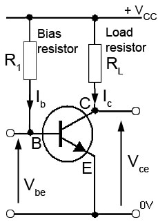
Let's take a step back and describe what an amplifier actually does and describe the behavior of amplifying devices. The "behavior" part will be critical to understanding amplifier classes. An amplifier takes a signal waveform and amplifies it (duh). In audio terms, that is to say, it makes it louder. We won't get into the details of how they function, but suffice it to say the main goal of the amplifier is to preserve the shape and frequency of the waveform while increasing the amplitude(it also inverts the waveform, but we will ignore that effect for the purpose of this discussion). We will call this preservation "fidelity." The increase in amplitude is called "gain." Ironically, for the subject of this discussion, it's best to assume that the gain for the amplifiers we are discussing is 1, or no change in amplitude, so from here on out, all gain in the rest of the discussion will be 1. Typical amplifying devices are things like vacuum tubes, BJT's, FET's, MOSFET's and various other oddball transistors.
Now on to behavior. Prepare your visual mathematics skills. The following graph is the mutual characteristic curve of a BJT (for simplicity assume all other amplifiers look similar). Simplified, it represents the output (vertical axis) with respect to the input (horizontal axis) for an amplifier. The most important thing to notice is that above 750mV input, the line is looking very straight and can be approximated as linear, that is to say "what goes in comes out," so it would be nice if our audio input signal could hang out on that part of the graph.

What is Bias and why we need it
Recall that audio signals are AC in nature so their voltage swings both positive and negative. Well that is obviously a problem with the above graph because we would get NO CURRENT output at anything below 600mV and some pretty yucky distortion between 600mV and 750mV. In other words, more than half of your signal would be gone entirely. In order to fix this, we add bias to the signal. Bias is very simply a constant DC voltage that we add to to the signal to bump up the range that it swings through. For the above graph, we would add bias 'til the lowest AC voltage would still land in the linear portion of the curve. For example: If our AC audio signal sometimes dips down to -900mV we would need to add a standing 1650mV (1.65V) DC voltage to the input to make sure the signal never dips below 750mV.
Would you look at that? We accidentally set the DC bias to a position that is called:
Class A
That's right, the above example where the bias is set such that the entire signal waveform is produced on the output is called Class A. So there we have it. Done deal. "Perfect" fidelity. Here is the graphical representation of Class A with the bias point labeled as Q.
Waveform looks and sounds great, but there is a bit of an issue...
That constant DC bias means that the amplifier is always on. Even when there is no signal, the amplifier is seeing an input voltage and vomiting out a massive amount of current and since we don't want to send that DC current out to our drivers, we have to dissipate it in the electronics as heat. This is why Class A amplifiers are hot and inefficient. Theoretically they can be near 50% efficient, but in practice they are more like 25%-30% efficient. That is to say the vast majority of the power that a Class A amp outputs goes to heating your room and only a small fraction is used to actually make sound come out. This puts a huge limit on the output power capability of a Class A amp. The more audio output power you want, the bigger and heavier the amp needs to be to dissipate the massive amount of heat so we don't cook the amp to a crisp. For example, if you buy yourself a 100Wpc (200W total power output) Class A stereo amp, you have also received a free 400W+ space heater that weighs 100lbs. Fortunately, there is a way to eliminate this problem entirely and that's called:
Class B
Why are we even talking about Class B? There are no Class B audio amplifiers. Well we need to so we can understand other stuff later. Let's dally briefly. Class B chooses to have no bias. In other words, Class B just ignores the whole purpose of bias so that it only outputs when the input signal goes above 600mV. It looks like this:
Yuck! More than half of my music is missing entirely! Let's call this "Garbage" fidelity. This will obviously sound really bad and it's why it's not ever used as an audio amplifier, but maybe we can make it better using some implementation shenanigans.
Using the above implementation, it's actually possible to preserve the positive and negative sections of the signal with no bias. You may have heard of it as it's called "Push-Pull." There are lots of other ways to implement this, but this one should be good enough to show the principle. One amplifier takes care of the positive side of the waveform and the other takes care of the inverted negative side and they are recombined back at the output. Fixed!
BUT, if you remember the characteristic curve, below 600mV there is no output at all so there is a 1.2V band(+600mV and -600mV) around 0V input where we get no audio as well as non-linearity until we get back to ±750mV. That looks like this:
So, it's still not good because we are still missing audio information at the 0V crossover point. But it is possible to make it better by using our old friend DC bias. If we add DC bias little by little, the signal will slowly fill in the pink dead zone shown above and when that zone is fully filled in, we call it:
Class AB
Adding just enough bias to fill in the dead zone looks like this:
We can call this "Slightly-Less-Garbage" fidelity. However, it's just enough bias to push the waveform high enough that when we combine the inverted waveforms again, it looks like this:

The above is idealized, but if the transistors are perfectly matched, the waveform can be reproduced perfectly. This is further helped by the fact that when both transistors are conducting in the crossover, they tend to cancel out their non-linearity. Sometimes physics is nice like that. So we have reconstructed "Perfect" fidelity. This can obviously be used for audio amplification and has the added benefit of the DC bias being much lower than Class A and hence, much more efficient. Typically, an efficiency of 60% is seen in Class AB.
Class D
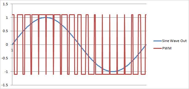
Forget everything we just talked about. What if we used our transistor in a completely different way. What if we just switched it on and off at hilarious speed in order to generate a pulse width modulated (PWM) signal? If you compare the input to a triangle wave, you can decide when to turn the transistor fully on and fully off. It looks something like this:

Let's call this "LOL, sure" fidelity. It seems pretty clear that the entire signal has been decimated, however, it can be fully recovered by running the square wave output through a low pass filter to get rid of the high frequency PWM noise. The low pass filter basically averages the on and off time to regenerate the original signal looking like this:
Again we have reconstructed "Perfect" fidelity. But why go through all the fuss of this encode-decode garbage and additional complication? It always comes back to efficiency. Because of the way transistors work, they are at their most efficient when fully off as well as when they are fully on. This is because when they are fully off, they act as an open loop (doing nothing) and when they are fully on they act as a short circuit, that is to say, they are basically a wire, and wires don't consume a lot of power, they just pass it on. This property of transistors means that the theoretical efficiency of a Class D amplifier is around 100% although the practical efficiency is more like 90%, which is still damn good. This efficiency is why most multichannel receivers are almost exclusively Class D. Putting out 100W to 5+ channels would get very toasty using any other amplifier.
So what does this all mean?Basically, the takeaway is that the only reason Class AB and Class D exist is due to efficiency. If physics had worked out in a way that a full fidelity, linear amplification scheme had very high efficiency, the other classes wouldn't be needed. However, in the world we live in, if you want an extremely powerful amp that won't burn your house down, you're going to have to look somewhere other than Class A. The fortunate thing is that engineers are smart doods and they figured out a way to take garbage, slightly-less-garbage and complete buffoonery and recombine them into "perfect" fidelity audio.
Beware!
This entire explanation is painfully simplified when compared to actual amplifier implementation. There is so much more going on in amps than just this. Realize that from a theoretical standpoint, all of these schemes can reproduce audio signals perfectly. Notice how I used the word "Perfect" in quotes, repeatedly. This is due to caveats with every implementation. Each of these designs requires a massive host of supporting electronics to prevent these things from becoming oscillators and to deal with the inherent distortion of every design. Even "Perfect" fidelity Class A can be ruined by improper treatment and implementation.
Resources:
https://techdocs.altium.com/cn/display/AMSE/SPICE+Model+Creation+from+User+Data
https://www.electronics-tutorials.ws/transistor/tran_2.html
http://www.learnabout-electronics.org/index.php
https://www.allaboutcircuits.com/textbook/experiments/chpt-6/class-b-audio-amplifier/
https://vanatoo.com/audiospeak/class-d-amplifiers/
https://www.soundonsound.com/techniques/what-class-d-amplification
https://en.wikipedia.org/wiki/Power_amplifier_classes
Designing Audio Power Amplifiers - Bob Cordell ISBN:978-0071640244
Hang on, who am I and what do I know about amplifiers?
I am a mechanical engineer working in aerodynamics. That is to say, decidedly the wrong engineer to discuss this topic. However, I was required to take Engineering Circuits at university to get my degree and the final project was actually to design and build an audio amplifier. In other words, I know just enough to be dangerous while having the ability to understand the concepts and complications involved. Audio has reignited my interest in electronics so I have been going back and re-learning it all.
That being said, I AM IN NO WAY AN EXPERT ON THIS SUBJECT. This is just what I have learned in my recent re-exploration.
The format.
In this thread I will go over the basics of several different amplifier classifications. Focus will be on Class A, B, AB and D. I will start with the science facts of what makes those classes and try to explain what those science facts mean to a layperson, focusing on the effect of said classes on audio amplification. That will dally ever so slightly into amplifier implementation, but I will try to explain it as simply as possible.
What do YOU need to bring.
It would help if you have some basic understanding of electricity (AC vs DC). You will be further served if you understand basic electronic components (resistors, capacitors, etc.) and how they interact with the electricity mentioned just previously. Beyond that come with an open mind for some learning and friendly discussion on the topic of amplification.
This thread and this post are not intended to be static!
If I screw something up, please call me out on it and provide supporting evidence contrary to the information I put forth. It would be great if people could use this post as a reference when deciding what amplifier to buy. It might even aspire to the heights of being used as a bludgeon in arguments on other forums (we can only hope.) If the discussion gets detailed enough, I would entertain adding the details in a section on the deeper implementation of these amplifier classes.
SO LET'S BEGIN WITH... Wait, what exactly is an amplifier?
Let's take a step back and describe what an amplifier actually does and describe the behavior of amplifying devices. The "behavior" part will be critical to understanding amplifier classes. An amplifier takes a signal waveform and amplifies it (duh). In audio terms, that is to say, it makes it louder. We won't get into the details of how they function, but suffice it to say the main goal of the amplifier is to preserve the shape and frequency of the waveform while increasing the amplitude(it also inverts the waveform, but we will ignore that effect for the purpose of this discussion). We will call this preservation "fidelity." The increase in amplitude is called "gain." Ironically, for the subject of this discussion, it's best to assume that the gain for the amplifiers we are discussing is 1, or no change in amplitude, so from here on out, all gain in the rest of the discussion will be 1. Typical amplifying devices are things like vacuum tubes, BJT's, FET's, MOSFET's and various other oddball transistors.
Now on to behavior. Prepare your visual mathematics skills. The following graph is the mutual characteristic curve of a BJT (for simplicity assume all other amplifiers look similar). Simplified, it represents the output (vertical axis) with respect to the input (horizontal axis) for an amplifier. The most important thing to notice is that above 750mV input, the line is looking very straight and can be approximated as linear, that is to say "what goes in comes out," so it would be nice if our audio input signal could hang out on that part of the graph.
What is Bias and why we need it
Recall that audio signals are AC in nature so their voltage swings both positive and negative. Well that is obviously a problem with the above graph because we would get NO CURRENT output at anything below 600mV and some pretty yucky distortion between 600mV and 750mV. In other words, more than half of your signal would be gone entirely. In order to fix this, we add bias to the signal. Bias is very simply a constant DC voltage that we add to to the signal to bump up the range that it swings through. For the above graph, we would add bias 'til the lowest AC voltage would still land in the linear portion of the curve. For example: If our AC audio signal sometimes dips down to -900mV we would need to add a standing 1650mV (1.65V) DC voltage to the input to make sure the signal never dips below 750mV.
Would you look at that? We accidentally set the DC bias to a position that is called:
Class A
That's right, the above example where the bias is set such that the entire signal waveform is produced on the output is called Class A. So there we have it. Done deal. "Perfect" fidelity. Here is the graphical representation of Class A with the bias point labeled as Q.
Waveform looks and sounds great, but there is a bit of an issue...
That constant DC bias means that the amplifier is always on. Even when there is no signal, the amplifier is seeing an input voltage and vomiting out a massive amount of current and since we don't want to send that DC current out to our drivers, we have to dissipate it in the electronics as heat. This is why Class A amplifiers are hot and inefficient. Theoretically they can be near 50% efficient, but in practice they are more like 25%-30% efficient. That is to say the vast majority of the power that a Class A amp outputs goes to heating your room and only a small fraction is used to actually make sound come out. This puts a huge limit on the output power capability of a Class A amp. The more audio output power you want, the bigger and heavier the amp needs to be to dissipate the massive amount of heat so we don't cook the amp to a crisp. For example, if you buy yourself a 100Wpc (200W total power output) Class A stereo amp, you have also received a free 400W+ space heater that weighs 100lbs. Fortunately, there is a way to eliminate this problem entirely and that's called:
Class B
Why are we even talking about Class B? There are no Class B audio amplifiers. Well we need to so we can understand other stuff later. Let's dally briefly. Class B chooses to have no bias. In other words, Class B just ignores the whole purpose of bias so that it only outputs when the input signal goes above 600mV. It looks like this:
Yuck! More than half of my music is missing entirely! Let's call this "Garbage" fidelity. This will obviously sound really bad and it's why it's not ever used as an audio amplifier, but maybe we can make it better using some implementation shenanigans.
Using the above implementation, it's actually possible to preserve the positive and negative sections of the signal with no bias. You may have heard of it as it's called "Push-Pull." There are lots of other ways to implement this, but this one should be good enough to show the principle. One amplifier takes care of the positive side of the waveform and the other takes care of the inverted negative side and they are recombined back at the output. Fixed!
BUT, if you remember the characteristic curve, below 600mV there is no output at all so there is a 1.2V band(+600mV and -600mV) around 0V input where we get no audio as well as non-linearity until we get back to ±750mV. That looks like this:
So, it's still not good because we are still missing audio information at the 0V crossover point. But it is possible to make it better by using our old friend DC bias. If we add DC bias little by little, the signal will slowly fill in the pink dead zone shown above and when that zone is fully filled in, we call it:
Class AB
Adding just enough bias to fill in the dead zone looks like this:
We can call this "Slightly-Less-Garbage" fidelity. However, it's just enough bias to push the waveform high enough that when we combine the inverted waveforms again, it looks like this:
The above is idealized, but if the transistors are perfectly matched, the waveform can be reproduced perfectly. This is further helped by the fact that when both transistors are conducting in the crossover, they tend to cancel out their non-linearity. Sometimes physics is nice like that. So we have reconstructed "Perfect" fidelity. This can obviously be used for audio amplification and has the added benefit of the DC bias being much lower than Class A and hence, much more efficient. Typically, an efficiency of 60% is seen in Class AB.
Class D
Forget everything we just talked about. What if we used our transistor in a completely different way. What if we just switched it on and off at hilarious speed in order to generate a pulse width modulated (PWM) signal? If you compare the input to a triangle wave, you can decide when to turn the transistor fully on and fully off. It looks something like this:
Let's call this "LOL, sure" fidelity. It seems pretty clear that the entire signal has been decimated, however, it can be fully recovered by running the square wave output through a low pass filter to get rid of the high frequency PWM noise. The low pass filter basically averages the on and off time to regenerate the original signal looking like this:
Again we have reconstructed "Perfect" fidelity. But why go through all the fuss of this encode-decode garbage and additional complication? It always comes back to efficiency. Because of the way transistors work, they are at their most efficient when fully off as well as when they are fully on. This is because when they are fully off, they act as an open loop (doing nothing) and when they are fully on they act as a short circuit, that is to say, they are basically a wire, and wires don't consume a lot of power, they just pass it on. This property of transistors means that the theoretical efficiency of a Class D amplifier is around 100% although the practical efficiency is more like 90%, which is still damn good. This efficiency is why most multichannel receivers are almost exclusively Class D. Putting out 100W to 5+ channels would get very toasty using any other amplifier.
So what does this all mean?Basically, the takeaway is that the only reason Class AB and Class D exist is due to efficiency. If physics had worked out in a way that a full fidelity, linear amplification scheme had very high efficiency, the other classes wouldn't be needed. However, in the world we live in, if you want an extremely powerful amp that won't burn your house down, you're going to have to look somewhere other than Class A. The fortunate thing is that engineers are smart doods and they figured out a way to take garbage, slightly-less-garbage and complete buffoonery and recombine them into "perfect" fidelity audio.
Beware!
This entire explanation is painfully simplified when compared to actual amplifier implementation. There is so much more going on in amps than just this. Realize that from a theoretical standpoint, all of these schemes can reproduce audio signals perfectly. Notice how I used the word "Perfect" in quotes, repeatedly. This is due to caveats with every implementation. Each of these designs requires a massive host of supporting electronics to prevent these things from becoming oscillators and to deal with the inherent distortion of every design. Even "Perfect" fidelity Class A can be ruined by improper treatment and implementation.
Resources:
https://techdocs.altium.com/cn/display/AMSE/SPICE+Model+Creation+from+User+Data
https://www.electronics-tutorials.ws/transistor/tran_2.html
http://www.learnabout-electronics.org/index.php
https://www.allaboutcircuits.com/textbook/experiments/chpt-6/class-b-audio-amplifier/
https://vanatoo.com/audiospeak/class-d-amplifiers/
https://www.soundonsound.com/techniques/what-class-d-amplification
https://en.wikipedia.org/wiki/Power_amplifier_classes
Designing Audio Power Amplifiers - Bob Cordell ISBN:978-0071640244
")