


Chrizo
New Head-Fier
- Joined
- Sep 19, 2007
- Posts
- 1
- Likes
- 0
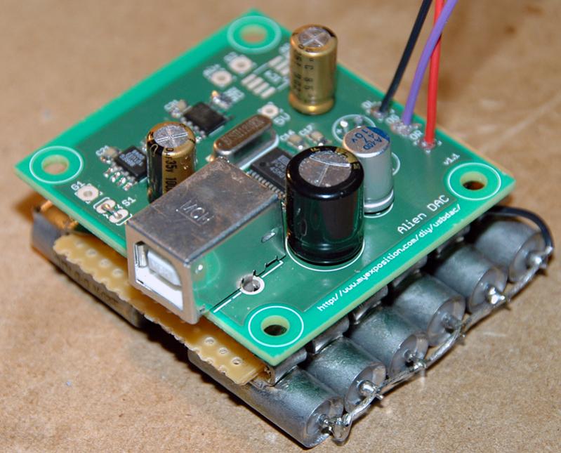
I build a Alien Dac too, but I have some problems. When attaching it to my PC it says 'Unknown device (device might be broken)'. Does anyone have an idea what i might have done wrong?
| Originally Posted by Chrizo /img/forum/go_quote.gif I build a Alien Dac too, but I have some problems. When attaching it to my PC it says 'Unknown device (device might be broken)'. Does anyone have an idea what i might have done wrong? |
| Originally Posted by dsavitsk /img/forum/go_quote.gif I tried it -- bypassing some pretty large electrolytics (330uF) with the 0.1uF 0805 film caps, I didn't hear much difference. Mind you, I didn't do a close comparison, the ratio between the caps may have been too large, and the electrolytics were solid organics (os-cons) which are better at high frequencies than the Muses. So I sill think bypassing the Muses might be worth the experiment, but in my case, it didn't seem to matter. |


| Originally Posted by Chrizo /img/forum/go_quote.gif I build a Alien Dac too, but I have some problems. When attaching it to my PC it says 'Unknown device (device might be broken)'. Does anyone have an idea what i might have done wrong? |
| Originally Posted by xmokshax /img/forum/go_quote.gif perhaps i'll still give those 0805 caps from Digi-Key a shot. unfortunately, i don't know that i'll ever use them again if the result isn't good, and Digi-Key makes you buy a minimum of ten
|
| Originally Posted by ezkcdude /img/forum/go_quote.gif These are such standard values for decoupling IC's, that if you do any smt PCB's in the future, you will need much more than 10. I bought 100 recently. Of course, the NP0/COG are more expensive than the X5(7)R. Still, these are generally used all over the place in electronics (not just audio). |

| Originally Posted by iewgnail /img/forum/go_quote.gif hi, i just build my alien dac. i got the 3v3 but on my 5v i'm getting 1.47v. where shld i look towards for debugging? |
