Alien DAC v1.1 Construction Thread
Aug 17, 2006 at 7:30 PM Post #226 of 1,562
Quote:

Originally Posted by deadlierchair
Alright, all of that is understood. I checked those two pins to see if there were any bridges but couldn't find anything. At this point I'm wondering if there are bad connections elsewhere on the board, if I soldered on an incorrect part, or if I possibly killed the PCM2702 with all that heat. I tried to get some better pictures but only had a little bit of luck.


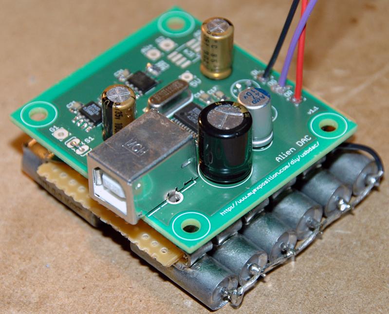
All components appear to be soldered correctly. You are most likely to have a short on 5V after IC3. It is either PCM2702 pins on the analog/right side or the SMD capacitors on the same side. I would triple check those (check under the pins too). Any other location is less likely. Anyway I suggest to clean the board and make sure that there is no traces of solder and flux anywhere on the board.

If all this does not help, find a thin screwdriver or a needle and clean/scratch between PCM2702 pins and tiny traces around it. If this does not help either, well, I am afraid it would be about time to start working on another board.
 
Aug 17, 2006 at 7:35 PM Post #227 of 1,562
Quote:

Originally Posted by splaz
Well got on the 2nd group buy and am sourcing parts.

For CL/CR. Two caps that I can actually get for that are

Nichicon FG 47uF

or

Elna Starget 22uF

either of them worth considering ?


If you cannot get hi-end electrolytics, go for larger film capacitors. Low-end electrolytics may sound nasty. You would be wasting your money and effort using those.
 
Aug 17, 2006 at 9:56 PM Post #229 of 1,562
Quote:

Originally Posted by abcheng
What would be the best quality cap for CL/CR with a reasonable price at digikey or mouser?


Elna RFS series from Digikey
To be more specific Part number #604-1054
problem is they are a little to big around to fit flat on the board.
 
Aug 17, 2006 at 10:09 PM Post #230 of 1,562
Quote:

Originally Posted by MisterX
Elna RFS series from Digikey
To be more specific Part number #604-1054
problem is they are a little to big around to fit flat on the board.


Thanks for the response
smily_headphones1.gif
. I'll definitely give those a try.
 
Aug 18, 2006 at 2:26 AM Post #232 of 1,562
I said pics would follow "soon", I guess i procrastinated a bit, so here it is finally.


The RCA jacks will be replaced by something nicer when I get around to case it up
smily_headphones1.gif
, probably, hah.

Not bad for 1st time smd eh? The white stuff is residue from cleaning with 99% isopropynol, any way to clean it properly? I was under the impression 99% would be pure enough not to leave residue, or is that residue flux that was dissolved by the alcohol but not cleaned off the board completely?
 
Aug 18, 2006 at 2:45 AM Post #233 of 1,562
Quote:

Originally Posted by Fiola
Not bad for 1st time smd eh?


Not bad at all.
smily_headphones1.gif


Quote:

or is that residue flux that was dissolved by the alcohol but not cleaned off the board completely?


Yup... that residue is the flux.
If you are using just alcohol and an old tooth brush you will have to clean it a couple of times to get that all off.
 
Aug 18, 2006 at 7:14 AM Post #236 of 1,562
Okay, sorry, may i rephrase my question?

The PCB has pads around where the can (now that i know thats the word
smily_headphones1.gif
) should be. On some PCB's ive seen it soldered. What is its purpose?

Rob.
 
Aug 18, 2006 at 7:37 AM Post #237 of 1,562
They do that for vibration and shock control.
Tall parts don't always play nice when shipped half way around the world and that is one solution you commonly see companies use to ensure they do.
Ever wonder why you see glue all over large capacitors in retail gear?
Same thing.
wink.gif
 
Aug 18, 2006 at 7:50 AM Post #238 of 1,562
Ohh... interesting, i didnt know that. I take it the reason that there are pads for crystals but not other tall/er parts is because they have metal cans and thus it makes sense?

[edit]: Also, is the improvement in overvolting the PCM2702 to 5.4v going to be noticable? Or better yet - to what extent do you think it might be noticable?

I see that the SNR raises a few dB, nothing to be writting home about. The THD, however, goes from .002 to .0015.... whats a .0005 difference like? (Jees, when you write it like that it doesnt seem like much)

Rob.
 
Aug 18, 2006 at 8:36 AM Post #239 of 1,562
Quote:

Originally Posted by MisterX
They do that for vibration and shock control.
Tall parts don't always play nice when shipped half way around the world and that is one solution you commonly see companies use to ensure they do.
Ever wonder why you see glue all over large capacitors in retail gear?
Same thing.
wink.gif


It also can dampen a circuit and improve sonic performance in some cases. This is especially noticable on speaker crossovers -- coat them in epoxy (or even better, take them out of the speakers and put them in thier own little boxes) and you will notice that the sound gets better. There are even some film caps that you can hook to a multimeter and watch the capacitance change as you squeeze them. This also happens as the air pressure in the speaker changes altering the crossover's filter points.
 
Aug 18, 2006 at 11:54 AM Post #240 of 1,562
Hi all,

I've built up my first (of 5) of these, and whilst it appears to work fine I get a lot of very audible noise - which almost sounds kinda looped?

The variant I've built is fed by a 9v battery and feeds the PCM chip 3.3v and 5.6v ( stuffed up my order of smt resistors and omited the K on the end of one of the values ) so had to use the next closest match I had.

I've used the 1A variety of the 1206 SMT Murata ferrite, but had to sub-out the 600R for the red LED for about 60R.

Other than that I'm using all std R values, and std C values for the smt capacitors. The electrolytics I'm using are: 470uf x1, 100uf x2, 47uf x1 and CR and CL are 10uf - all Nichicon FX.

The Crystal is this guy:
Digi-Key Part NumberX983-ND
Manufacturer Part NumberECS-120-32-1X
DescriptionCRYSTAL 12.000MHZ 32PF HC-49/UA

Help?
 

Users who are viewing this thread

Back
Top