Alien DAC v1.1 Construction Thread
Aug 15, 2006 at 3:57 PM Post #211 of 1,562
Quote:

Originally Posted by tomb
Good point - it would have to be a "fitted" piece of foam, and you'd have to insert the board and the backstop at the same time, with both in their mutual final position (assuming a longer piece of sheet stock). Most likely the USB solder tabs and the Hammond slots are more than enough to keep the joints/board from flexing.

I was just brainstorming ...


OK... here's MY take on this. I think he simply wedged the foam between the insert and the panel, putting a little pressure on the insert so it doesn't rattle and, I think, based on his rather cryptic post, giving adequate pressure with or without the plastic bezels mounted. His photo implies some other mysterious configuration but think that was just a trick
eggosmile.gif


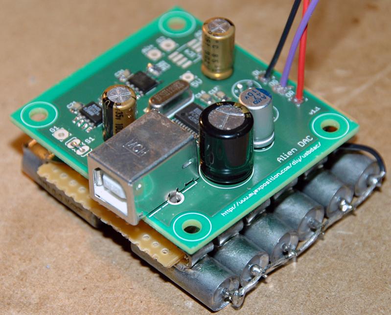
I am in the middle of building mine into the same or similar case and I was going to cut down some rat shack stripboard because I don't have any suitable scrap metal sheet laying around. I didn't think about the problem with the insert rattling, but I think I'll try wedging some foam in there, maybe glue it to the inside of the front panel to make things simpler to install and uninstall.
 
Aug 15, 2006 at 8:21 PM Post #213 of 1,562
Quote:

Originally Posted by MisterX
I dunno which is worse... the fact that I had to click to be insulted by the resident troll or the fact that he doesn't get it.
mad.gif


I didn't realize we had a problem. Sorry to hear that since I don't see anything offensive in my replies here. I don't think I've ever been called a Troll; not here or any other forum that I frequent.

confused.gif
 
Aug 16, 2006 at 1:51 AM Post #215 of 1,562
I was just thinking, since these boards use the immersion silver plating, should it be necessary to use silver-bearing solder to prevent the silver from leaching into the joint and weakening it? or is it too little to matter? I remember something about silver solder being originally developed for soldering joints containing silver
 
Aug 16, 2006 at 10:12 AM Post #216 of 1,562
Alright, time to look to the collective builders for help
wink.gif


Here is the story thus far: I built the DAC using IC3 to regulate but could never get anything to come through on the 5v so I figured that USB wasn't supplying enough voltage (4.82 on one PC, 4.96 on the other). In that configuration, the LED would light up and the DAC would recognize on the computer but there would be no sound output since the analog section of the chip wasn't receiving any power!

I decided to remove IC3, C32, R31, and R32 (jumpering AV+ to 5v) to see if it would help. Since that change, the LED no longer lights up and on both the 3.3v and the 5v I am receiving 50mv and 160mv - clearly something is wrong. On top of that, the computer no longer recognizes the device (I would bet because the 3.3v is no longer getting power!)

I have one question immediately: on the PCM2702, pins 16 and 17 show continuity. When I test one of my unpopulated boards, these pins are not connected. Could that be part of the problem? They showed continuity under my first config and now once I've removed regulation. Beyond that here are my pics, I wonder wonder wonder...


Aug 16, 2006 at 10:44 AM Post #217 of 1,562
Could you post bigger pictures? I believe you have some cold joints and some solder bridges. I would also clean the flux on the board with a toothbrush and some alcool.

Quote:

Originally Posted by deadlierchair
Alright, time to look to the collective builders for help
wink.gif


Here is the story thus far: I built the DAC using IC3 to regulate but could never get anything to come through on the 5v so I figured that USB wasn't supplying enough voltage (4.82 on one PC, 4.96 on the other). In that configuration, the LED would light up and the DAC would recognize on the computer but there would be no sound output since the analog section of the chip wasn't receiving any power!

I decided to remove IC3, C32, R31, and R32 (jumpering AV+ to 5v) to see if it would help. Since that change, the LED no longer lights up and on both the 3.3v and the 5v I am receiving 50mv and 160mv - clearly something is wrong. On top of that, the computer no longer recognizes the device (I would bet because the 3.3v is no longer getting power!)

I have one question immediately: on the PCM2702, pins 16 and 17 show continuity. When I test one of my unpopulated boards, these pins are not connected. Could that be part of the problem? They showed continuity under my first config and now once I've removed regulation. Beyond that here are my pics, I wonder wonder wonder...


Aug 16, 2006 at 11:47 AM Post #219 of 1,562
Quote:

Originally Posted by deadlierchair
I have one question immediately: on the PCM2702, pins 16 and 17 show continuity. When I test one of my unpopulated boards, these pins are not connected. Could that be part of the problem? They showed continuity under my first config and now once I've removed regulation. Beyond that here are my pics, I wonder wonder wonder..


Yes, you've shorted the regulated 5V to ground. The 3.3V reg, 5V reg, and LED come off the same line so in your original configuration you were simply shorting the 5V regulated line so 3.3V and the LED line were unaffected. Now, you're shorting everything. Read the datasheet!
 
Aug 16, 2006 at 1:08 PM Post #220 of 1,562
yeh, pin 17 is 5V, pin 13 - 16 is ground.
for a while i thought I had shorts between 13-16, used desoldering braid to make it really really clean and it was still shorted, then I read the spec sheet, doh! One of the gotchas if you didnt read the spec sheet I guess, heh
 
Aug 16, 2006 at 2:48 PM Post #221 of 1,562
Quote:

Originally Posted by deadlierchair
Alright, time to look to the collective builders for help
wink.gif


Here is the story thus far: I built the DAC using IC3 to regulate but could never get anything to come through on the 5v so I figured that USB wasn't supplying enough voltage (4.82 on one PC, 4.96 on the other). In that configuration, the LED would light up and the DAC would recognize on the computer but there would be no sound output since the analog section of the chip wasn't receiving any power!

I decided to remove IC3, C32, R31, and R32 (jumpering AV+ to 5v) to see if it would help. Since that change, the LED no longer lights up and on both the 3.3v and the 5v I am receiving 50mv and 160mv - clearly something is wrong. On top of that, the computer no longer recognizes the device (I would bet because the 3.3v is no longer getting power!)

I have one question immediately: on the PCM2702, pins 16 and 17 show continuity. When I test one of my unpopulated boards, these pins are not connected. Could that be part of the problem? They showed continuity under my first config and now once I've removed regulation. Beyond that here are my pics, I wonder wonder wonder...

[[/IMG][/URL]


Pin 16 is grounded and pin 17 carries +5V. The short across them is killing your +5V. Even if your PC delivers siginificantly less than 5V, if things were working correctly IC3 would just put out the USB voltage, less a small drop across the regulator. IOW, a slightly low USB voltage is NOT the problem. it is the short. If you can't see a short, try brushing between the pins with a toothbrush. It is possible a tiny wire strand fragment or some other metal is lodged beneath the pins.
 
Aug 16, 2006 at 4:45 PM Post #222 of 1,562
Quote:

Originally Posted by Fiola
yeh, pin 17 is 5V, pin 13 - 16 is ground.
for a while i thought I had shorts between 13-16, used desoldering braid to make it really really clean and it was still shorted, then I read the spec sheet, doh! One of the gotchas if you didnt read the spec sheet I guess, heh


I had a similar problem, two pins on the pcm2702 chip had a very small solder bridge and that was killing my analog section. I used a ton of flux, and the wipe method described earlier in this thread. It finally took a suggestion to hold the board up with a light behind it rather than shining on it for me to be able to see the bridge under a magnifier. Once I got it cleaned up (more flux, and more wiping) it worked great.
 
Aug 16, 2006 at 6:26 PM Post #223 of 1,562
Well got on the 2nd group buy and am sourcing parts.

For CL/CR. Two caps that I can actually get for that are

Nichicon FG 47uF

or

Elna Starget 22uF

either of them worth considering ?
 
Aug 17, 2006 at 1:21 AM Post #224 of 1,562
Quote:

Originally Posted by NeilR
Pin 16 is grounded and pin 17 carries +5V. The short across them is killing your +5V. Even if your PC delivers siginificantly less than 5V, if things were working correctly IC3 would just put out the USB voltage, less a small drop across the regulator. IOW, a slightly low USB voltage is NOT the problem. it is the short. If you can't see a short, try brushing between the pins with a toothbrush. It is possible a tiny wire strand fragment or some other metal is lodged beneath the pins.


Alright, all of that is understood. I checked those two pins to see if there were any bridges but couldn't find anything. At this point I'm wondering if there are bad connections elsewhere on the board, if I soldered on an incorrect part, or if I possibly killed the PCM2702 with all that heat. I tried to get some better pictures but only had a little bit of luck.

1.jpg
2.jpg
3.jpg
4.jpg
 
Aug 17, 2006 at 11:39 AM Post #225 of 1,562
Quote:

Originally Posted by splaz
Well got on the 2nd group buy and am sourcing parts.

For CL/CR. Two caps that I can actually get for that are

Nichicon FG 47uF

or

Elna Starget 22uF

either of them worth considering ?


I would refer to dsavitsk's site on capacitor reviews - it is listed in Alf's support pages with a tiny link on the word "here" when Alf is discussing capacitors.

I don't think either of the ones you mention were discussed. Nichicon ES and Elna Silmic are the closest ones, I think.
 

Users who are viewing this thread

Back
Top