Alien DAC v1.1 Construction Thread
Mar 25, 2007 at 5:06 PM Post #646 of 1,562
Quote:

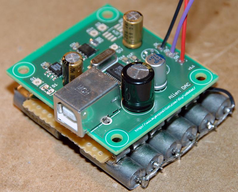
Originally Posted by GarlicKnots /img/forum/go_quote.gif
Both 27/28 are bridged. They both go to ground. I also bridged 13/14 since they go to ground. That is OK, I believe?


nope.

http://focus.ti.com/lit/ds/symlink/pcm2702.pdf

Pinout is on page 3

28 goes to the crystal.
27 is VccP

Its hard to tell from the photos but it looks like those might be bridged. If they are you could get that error message. If you have access to an oscilloscope you can check if the crystal is oscillating.

25 is VccL 24 is AGNDL -- Yeah if those were bridged, you wouldn't have a working +5V supply. My bad.
 
Mar 25, 2007 at 5:30 PM Post #647 of 1,562
Quote:

Originally Posted by GarlicKnots /img/forum/go_quote.gif
Q. If I'm getting 3.3 and 4.7, should I refrain from touching 2-9 and 16-26?


I was getting the right voltage on the regs but it was either pin 2 or 3 that was open and I had that exact same problem as you. In fact you should get the right voltages with or without the chip installed, so just because they're right, doesn't mean they're actually connected to the chip. Unless you mean you're measuring the voltage on each pin as what it should be, in which case there shouldn't be a need to do anything to those pins.
 
Mar 25, 2007 at 6:48 PM Post #648 of 1,562
Quote:

Originally Posted by AndrewFischer /img/forum/go_quote.gif
nope.

http://focus.ti.com/lit/ds/symlink/pcm2702.pdf

Pinout is on page 3

28 goes to the crystal.
27 is VccP

Its hard to tell from the photos but it looks like those might be bridged. If they are you could get that error message. If you have access to an oscilloscope you can check if the crystal is oscillating.

25 is VccL 24 is AGNDL -- Yeah if those were bridged, you wouldn't have a working +5V supply. My bad.


Andrew, you're correct, my number configuration was incorrect. I thought the pin across from pin 1 was pin 15, it's pin 28.

I'm bridging 13/14 and 15/16 by the correct pin out diagram. Those go to ground.

I did some more resoldering, etc.

I plugged it in and it actually recognized it at first as USB speaker, burr brown, etc.

The 3.3 rail was correct.

However the 5v rail was registering .1.

I unplugged, replugged and this time it didn't recognize.

More soldering, eh? Hopefully, I didn't burn the chip.

f/R
 
Mar 27, 2007 at 6:24 AM Post #649 of 1,562
I finally got around to populating two of my boards from the 2nd group buy today after free time suddently manifest.
smily_headphones1.gif
Both work great, though one malfunctioned due to some solder bridges on the 2702 and a mistake soldering the oscilator connections.

I'd like to case them up with some existing amplifiers now, but I don't have panel space to put the PCB against it.

Can someone please direct me to a panel mount usb jack?

---------
When I was debugging the 'bad' board, windows also gave me a malfunctioning usb device error. I suggest that you measure the voltage of the two pins at closest to the crystal. They should be about 1.5V each. If they are not, the the 2702 will not function properly because its clock is malfunctioning. R14/C11/C12 on the bottom side also need to be checked. This was how I figured out what the problem was - a bad solder joint on the bottom side of the board. I hope that this helps.
 
Mar 28, 2007 at 5:55 PM Post #653 of 1,562
Quote:

Originally Posted by error401 /img/forum/go_quote.gif
Ooops! So sorry Alf, I knew it was a 3-letter name starting with a, and yours came to mind.


Yes, I had boards made with Alf's help. They are now ready along with my kit.

BOM and email address can be seen here:

http://www.geocities.com/jeffrossel/

I will try to get in touch with all the people who contacted me, but if I miss you please Email me.
 
Mar 28, 2007 at 6:34 PM Post #655 of 1,562
Quote:

Originally Posted by splaz /img/forum/go_quote.gif
Reading the list of parts I see at the bottom it has an option for bare boards, no price though. This a yet to be added option ?


The price for bare boards is 2.00 each (close to my cost), which is less than the previous group buy due to my not having to pay VAT.

JR
 
Mar 29, 2007 at 2:20 AM Post #657 of 1,562
[nvm first part]

The windows does not recognize this device errors--try checking continuity between the USB pins. One of my DACs had that shorted, and Windows couldn't ever detect it properly. I found out that the short was likely under the PCM2702 somewhere, and honestly I just gave up on that DAC. If you're lucky, your problem is somewhere obvious; otherwise, you've got quite a bit of desoldering to do =(
 
Mar 29, 2007 at 7:03 AM Post #658 of 1,562
Quote:

Originally Posted by dakotart1984 /img/forum/go_quote.gif
Snoopy: Mouser part# 568-NAUSB-B Neutrik quality there, and they also have it in silver

And what BOM did you go by


On order.
frown.gif


I used this one (see attached). There are a few items not listed because I already had them (usb jacks & output DC blocking caps).

------------------------------
I found another panel mount usb option: http://www.datapro.net/products/1591.html

-------------------------------
Mr X:

Is this the high quality rca jack that you referred to?

http://www.l-com.com/item.aspx?id=1008

As far as I can tell, it is just a single jack and they don't seem to offer different color choices (red/white/black). Is this correct or am I not looking hard enough?
 

Users who are viewing this thread

Back
Top