


Reactcore
Headphoneus Supremus
Hello readers,
I created this thread to share with others my insight on how to built in an analog input into an digital only dac/amp.
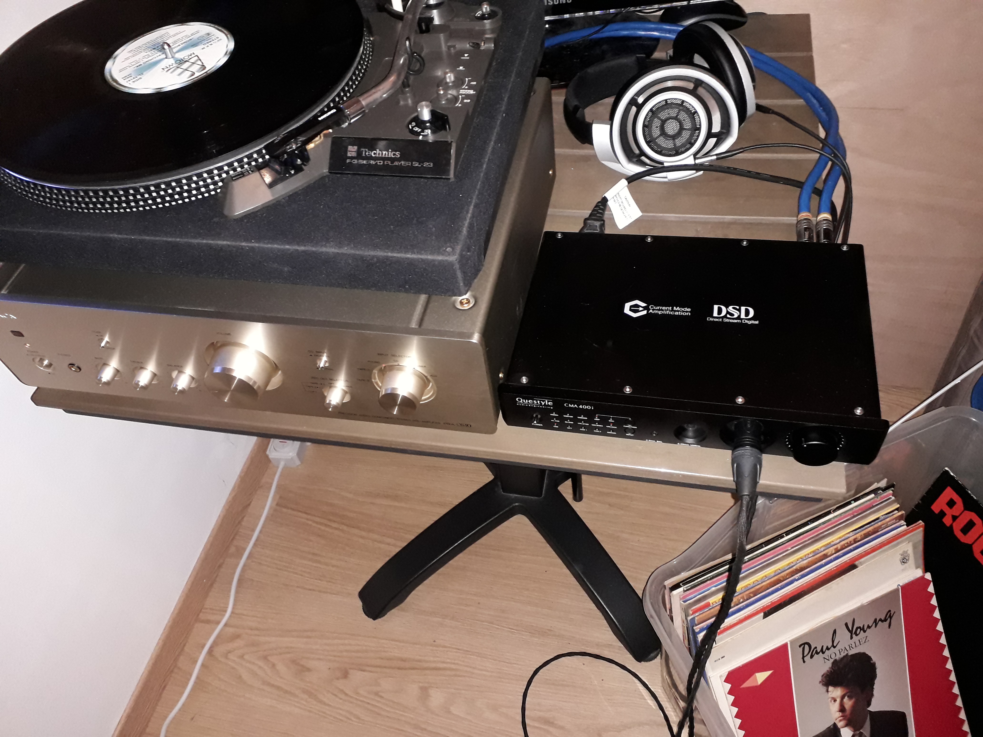
I had my eye (or should i say ears) on a Questyle CMA400i and CMA Twelve DAC-AMP unit which i auditioned in a store.
i found this thing sounding exceptional with its patented 'Current mode' amplifier. only i had to find out it didn't had an analog input so i could'nt connect my separate dac. it meant my only option was to go with the older CMA600 if i wanted to also have an inbuilt dac to choose. or go with a amp only which was way more expensive.
So i pulled my trigger on a 2nd hand CMA400 for €400 knowing i was going to modify it.

So lets start.
Needed items:
Unsolder the volume potmeter using desoldering litze.
Tip: you can also use thick massive wire between the pins and heat up all six contacts at once using lots of solder.

Now cut off the right 2 pins really short as in the picture.

On the PCB, solder 2 wires into the right holes (where the cutted pins were)

Solder 2 short wires on the side of the cutted contacts of the pot and place it back on the PCB, be sure it is straight mounted.

I want to place the relay as close as possible to the potmeter to prevent signal degradation
So in order to create room for the relay i moved one trasistor to the bottom side of the PCB and the second bowed.

Now its time to place the relay and connect the wires, first i soldered the twin wire for the coil

From top to bottom youll see on the relay:
Normally open pins for the analogue input,
Preamp section of the PCB connected to the normally closed pins,
Common contact connected to the potmeter
Twinwire connected to the coil pins
front side view, pay attention that the cutted part and the PCB aren't toughing.
under you'll see there's space for the moved transistor.

Now assemble the unit back together without the top.
Drill the holes and place the switch as you see at the right side.above the Spdif out RCA.
Pay good attention that the holes are centered with enough space around to mount the RCA's and switch.
I laid the unit upside down so metal drill residue won't fall into the electronics.

Now solder one of twin wire from the relay coil on the switch, the other wire just let it go passing by.

Then solder the twin wire to the DC power input of the digital section.
It is the right pair of diodes, the polarity makes no difference.

Place the RCA's into the holes on the back.
be sure they are isolated from the chassis to prevent ground loops and noise.
They come with special plastic rings for that.

Then connect the signal wires between the relay and the RCA's
This is the shortest route possible for the analog audio signal.

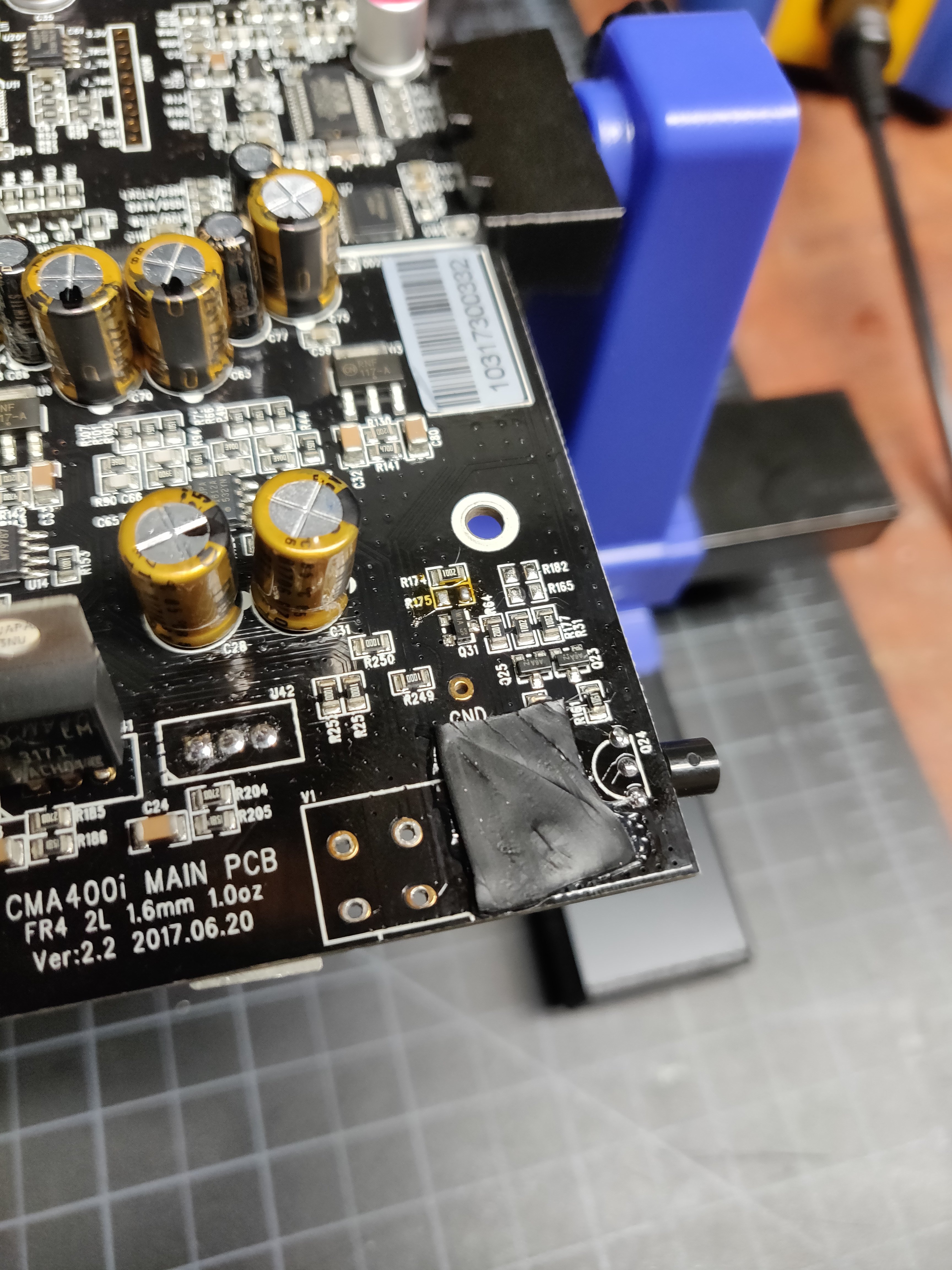
Just behind the potmeter there is a test pin marked with GND (signal ground)

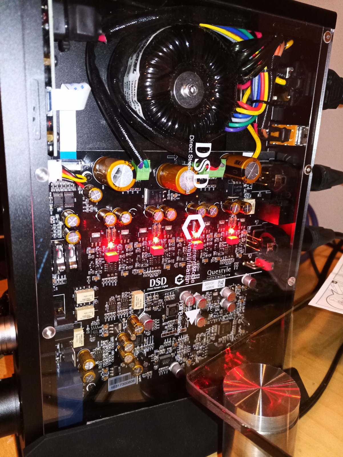
Final inside

Now close the top and youre in for a nice listening with your favorite DAC of choice and a Current mode amplifier")
Rear view of finished product:


This can be done with most amp/dac brands with a analogue potmeter or resistor ladder with line level pass through, they work pretty much the same.
For the ones interested i include a schematic.
The blue part is original, and red marked is the addon part.

I created this thread to share with others my insight on how to built in an analog input into an digital only dac/amp.
I had my eye (or should i say ears) on a Questyle CMA400i and CMA Twelve DAC-AMP unit which i auditioned in a store.
i found this thing sounding exceptional with its patented 'Current mode' amplifier. only i had to find out it didn't had an analog input so i could'nt connect my separate dac. it meant my only option was to go with the older CMA600 if i wanted to also have an inbuilt dac to choose. or go with a amp only which was way more expensive.
So i pulled my trigger on a 2nd hand CMA400 for €400 knowing i was going to modify it.
So lets start.
Needed items:
- Soldering iron with solder and litze for desoldering.
- Pair of side cutting pliers, screwdrivers
- Good quality relay (i used a NEC MR62-12SR with goldplated internal contacts)
- Twin wire for power to the relay
- Good quality shielded wire for audio signal transport to the RCA connectors on the back
- One pole miniature toggle switch for one hole mounting
- 2 good quality isolated RCA female chassis connectors hole mounting
- Drill machine and 6mm and 10mm drills
- Good light on your workplace
- A multimeter to check.
Unsolder the volume potmeter using desoldering litze.
Tip: you can also use thick massive wire between the pins and heat up all six contacts at once using lots of solder.
Now cut off the right 2 pins really short as in the picture.

On the PCB, solder 2 wires into the right holes (where the cutted pins were)

Solder 2 short wires on the side of the cutted contacts of the pot and place it back on the PCB, be sure it is straight mounted.

I want to place the relay as close as possible to the potmeter to prevent signal degradation
So in order to create room for the relay i moved one trasistor to the bottom side of the PCB and the second bowed.

Now its time to place the relay and connect the wires, first i soldered the twin wire for the coil

From top to bottom youll see on the relay:
Normally open pins for the analogue input,
Preamp section of the PCB connected to the normally closed pins,
Common contact connected to the potmeter
Twinwire connected to the coil pins
front side view, pay attention that the cutted part and the PCB aren't toughing.
under you'll see there's space for the moved transistor.

Now assemble the unit back together without the top.
Drill the holes and place the switch as you see at the right side.above the Spdif out RCA.
Pay good attention that the holes are centered with enough space around to mount the RCA's and switch.
I laid the unit upside down so metal drill residue won't fall into the electronics.

Now solder one of twin wire from the relay coil on the switch, the other wire just let it go passing by.

Then solder the twin wire to the DC power input of the digital section.
It is the right pair of diodes, the polarity makes no difference.

Place the RCA's into the holes on the back.
be sure they are isolated from the chassis to prevent ground loops and noise.
They come with special plastic rings for that.

Then connect the signal wires between the relay and the RCA's
This is the shortest route possible for the analog audio signal.

Just behind the potmeter there is a test pin marked with GND (signal ground)

Final inside
Now close the top and youre in for a nice listening with your favorite DAC of choice and a Current mode amplifier
Rear view of finished product:
This can be done with most amp/dac brands with a analogue potmeter or resistor ladder with line level pass through, they work pretty much the same.
For the ones interested i include a schematic.
The blue part is original, and red marked is the addon part.
Last edited:


