


00940
Headphoneus Supremus
- Joined
- Nov 6, 2002
- Posts
- 4,493
- Likes
- 47
When I first started visiting head-fi, the Audiovalve RKV was one of the "ultimate" amplifiers you could get. Later on, I was lucky to find an early kit from Elrad, based on the same schematic (which can be found here , along with many explanations about the rkv). I've since sold this one but I still kind of regret it. So I tought that it might be interesting to consider building something similar but not a complete clone (that wouldn't be fun).
The RKV uses a highly heretic approach: a complete tube amplifier (gain stage, inverter, output stage) inside the loop of a pedestrian opamp. It has advantages: high psrr, stabilization of the tubes operating points even as they age, linearization of the amp leading to very low thd, reduction of the output impedance. It used 4 pcl805, which have a weak triode section (used for gain stage and inverter) and a strong pentode section (used for the output stage), strong enough to drive the AKG K1000. The RKV has also some points which aren't that great. The main one is that the amplifier has very high gain (almost 50x). Why ? The amp can only be made stable if the opamp is set to have more gain than the input tube. The PCL805 has very high µ (60). Another problem is that they used a quite complex power supply to get bipolar supplies and various bias voltage. It can be made simpler (somehow).
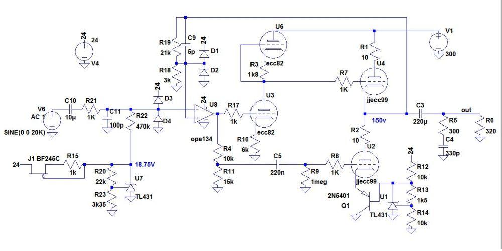
Here's a preliminary schematic:

Let's get rid of the pcl805, with its high µ triode. Most triode-pentode tubes have high µ triodes, so they're all out. For the input stage, a common lowish µ triode is the ecc82/12au7, with a µ at about 17-20 (at best). Still a bit high but it can be reduced with the use of an unbypassed srpp. It will provide a voltage gain of about x5. The opamp gain can now be reduced from 50 to 8. This adds a triode. But to stay with two tubes per channel, I can remove the inverter and drive the lower output tube directly from the opamp. While I'm at it, let's dc couple the srpp to the output stage. What about the output tubes ? The pcl805 was more powerful than needed for almost all headphones. An ECC99 or 6N6P is probably a sensible replacement. At 20ma/150V, they can run at 3W each (well, one runs at 4w since it has to drive the feedback network). Still under the 8W total power of the tube. It could probably run at 15ma/130v.
To simplify the power supply, all the negative supplies have been shifted to gnd. The lower gain imposes a higher voltage reference at the input, which means that the opamp can do with a 0-24vdc supply. The output is now biased from the cathode (and can be adjusted easily). The ecc82 heaters can be supplied from the same 24V supply through a cheap switching reg (plenty of lm2596 boards on ebay). The 6n6p will require an elevated heater (the vhk max is 100v).
Of course, this could be even simpler and better, Torpedo inspired With a ecc99 instead of the ecl84, you'd loose some gain but you'd need only one tube.

So what do you guys think? Waste of time ? Worth trying one or the other ?
The RKV uses a highly heretic approach: a complete tube amplifier (gain stage, inverter, output stage) inside the loop of a pedestrian opamp. It has advantages: high psrr, stabilization of the tubes operating points even as they age, linearization of the amp leading to very low thd, reduction of the output impedance. It used 4 pcl805, which have a weak triode section (used for gain stage and inverter) and a strong pentode section (used for the output stage), strong enough to drive the AKG K1000. The RKV has also some points which aren't that great. The main one is that the amplifier has very high gain (almost 50x). Why ? The amp can only be made stable if the opamp is set to have more gain than the input tube. The PCL805 has very high µ (60). Another problem is that they used a quite complex power supply to get bipolar supplies and various bias voltage. It can be made simpler (somehow).
Here's a preliminary schematic:
Let's get rid of the pcl805, with its high µ triode. Most triode-pentode tubes have high µ triodes, so they're all out. For the input stage, a common lowish µ triode is the ecc82/12au7, with a µ at about 17-20 (at best). Still a bit high but it can be reduced with the use of an unbypassed srpp. It will provide a voltage gain of about x5. The opamp gain can now be reduced from 50 to 8. This adds a triode. But to stay with two tubes per channel, I can remove the inverter and drive the lower output tube directly from the opamp. While I'm at it, let's dc couple the srpp to the output stage. What about the output tubes ? The pcl805 was more powerful than needed for almost all headphones. An ECC99 or 6N6P is probably a sensible replacement. At 20ma/150V, they can run at 3W each (well, one runs at 4w since it has to drive the feedback network). Still under the 8W total power of the tube. It could probably run at 15ma/130v.
To simplify the power supply, all the negative supplies have been shifted to gnd. The lower gain imposes a higher voltage reference at the input, which means that the opamp can do with a 0-24vdc supply. The output is now biased from the cathode (and can be adjusted easily). The ecc82 heaters can be supplied from the same 24V supply through a cheap switching reg (plenty of lm2596 boards on ebay). The 6n6p will require an elevated heater (the vhk max is 100v).
Of course, this could be even simpler and better, Torpedo inspired
With a ecc99 instead of the ecl84, you'd loose some gain but you'd need only one tube.So what do you guys think? Waste of time ? Worth trying one or the other ?
 I don't think it is as "cool" as the previous circuits, as the opamp doesn't set the operation point of the tubes. But it sims good.