A look at materials for magnetic shielding
Mar 5, 2018 at 2:53 PM Thread Starter Post #1 of 17

milosz

500+ Head-Fier
Joined
Aug 17, 2009
Posts
971
Likes
121
Some headphone amps that I've built have had very low -but audible- levels of 60 Hz hum when the level was cranked way up.

No one listens that way- with the volume at 11- unless you have VERY inefficient 'phones like HE-6 or K-100's, and with those inefficient drivers you won't hear that low-level hum.

So while it's not a problem with using these amps, I thought it would be interesting to see if materials could be found to shield against this inductively coupled* 60 Hz noise.

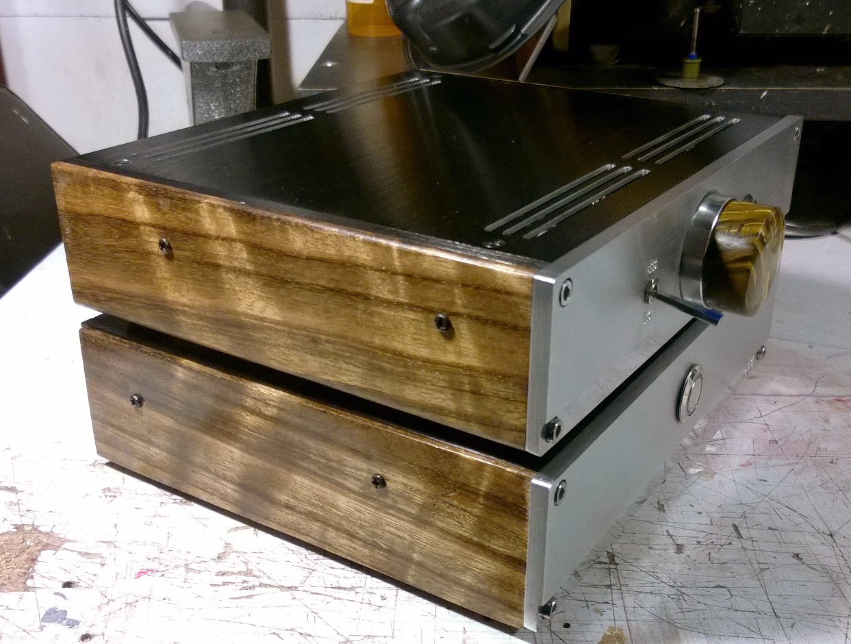
The Beta 22 is a very fine headphone amp. Most of the builds that you see are "two box" builds, meaning separate chassis for the amplifier and the power supply sections. There's two good reasons for that:

One is that with two separate boxes, you can isolate the "audio ground" from the AC line "safety ground" - that ground coning in on the third pin of your AC cord is often plagued with noise of various types, it's best to keep that isolated from signal ground. With a 2-box build you can do that- use the safety ground on the chassis of the power supply to improve safety in the even that the power transformer primary or some AC input wiring shorts to the case, while at the same time having the signal ground connected to the case of the amp section to drain capacitively coupled noise currents away.

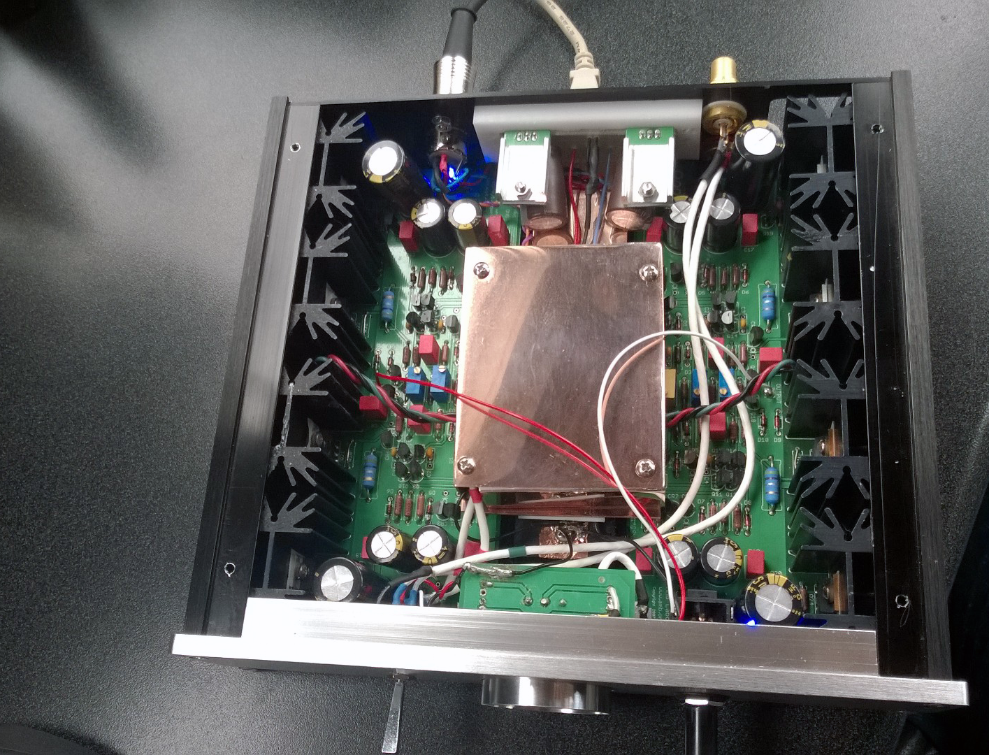
The other is that the Beta 22 amp circuits are relatively sensitive to inductively coupled noise. I don't know why the Beta 22 seems more sensitive to sonic intrusion from alternating magnetic fields than some other designs, but this does seem to be the case. A 2 box build lets you place the power transformer some discrete distance from the amp boards, which eliminates this hum pickup.
Having a 2-box Beta 22 on hand I thought it would be a good tool to test ways to shield against magnetic interference.

METHOD:

1. Connect a pair of sensitive IEMs to the Beta 22 output.
2. Place the amp chassis atop the power supply chassis. (Note the amp chassis has rubber feet which electrically isolates the two chassis when placed this way.
3. Listen.

NOW for the test:

Place the material under test atop the sigma 22 power supply chassis and then place the beta 22 amp on top of that, have a listen and see if hum is diminished.
I tested a number of materials. Here are my observations:

1. 99.99% pure iron sheet. 0.2 mm thickness
RESULT: some reduction in hum

2. "High purity" nickel sheet 0.1 mm thick
RESULT: no discernible reduction in hum

3. Mu Metal sheet 0.3 mm thickness
RESULT: Essentially complete elimination of hum

3. Mu Metal sheet 0.1 mm thickness
RESULT: some reduction of hum

4. Metglas amorphous film, 0.02 mm thick
RESULT: significant reduction in hum

5. Giron sheet
RESULT: Nearly complete reduction of hum
I realize these results are expressed in relative, non-quantitative terms and that the experiment design is imperfect, not controlling for all the possible variables. I tried to measure the hum using an oscilloscope but there was so much RF hash on the signal that I could not capture changes in magnitude of the 60 Hz component. ( I live near an FM station, there's a lot of ~100 MHz RF in the air around here.) I suppose I could capture data from the 'scope to my PC then use FFT to tease out the 60 Hz component but I'm too lazy.


* You can hear the difference between capacitively coupled 60 Hz noise and inductively coupled noise - the capacitively coupled noise is essentially connecting through a high-pass filter and you'll hear the "buzz" of all the harmonics and very little of the 60 Hz fundamental. An inductively coupled power line noise, in contrast, has more "hum" than buzz because it is essentially connecting to your audio circuit by a low-pass filter.
 
Mar 6, 2018 at 2:17 PM Post #3 of 17
RE: RFI

Typically there is no internal source of RFI inside an audio component (there are exceptions, see below) - most EMI is capacitively coupled from the outside at high frequencies. The typical aluminum enclosure used for most audio gear does an adequate job shielding the stray RF that is present in most listening environments- most listening rooms are kilometers distant from strong HF or VHF radio sources. There are exceptions - I live (essentially) right on top of an FM station's transmitting site, so no matter what I do there is ~100 MHz RF floating on everything. I can see it, and measure it's frequency, with my 'scope.

By and large, it does not impact headphone listening. However some "speaker" type gear has problems, I think this is due to the longer cables & speaker wires, etc. Typically what you get is some saturation of gain elements - they are trying to amplify 100 MHz RF but it is outside their ability, and you get problems. You normally hear this as a particular kind of 60 Hz-overtone buzz. I do not know why it's 60 Hz. Perhaps the FM station has some 60 Hz AM in it's output - it's an FM station, after all, so a tiny little AM on the carrier wouldn't cause any trouble.

This is particularly troublesome on my vinyl rig (speakers, not 'phones. ) Large amounts of gain and some unshielded wires in the cartridge head area make for RFI problems. I've also used a copper plated steel rod driven eight feet into the soil that is kept wet by a rain gutter downspout, connected to the audio gear by very heavy woven copper grounding strap which is the equivalent of 0000 AWG... but at 100 MHz even this thick cable has enough reactance to prevent draining the stray RF currents to ground. I've tried putting LC filters on the input of the phono preamp (small ferrite choke in series with the audio with a small silver-mica capacitor to ground from the audio line... -6 dB per octave@ 300 KHz... - 60 dB @ 100 MHz ) to no avail. I've concluded that the only solution would be to line the walls floor and ceiling of my room with copper, make it a Faraday cage....

INTERNALLY GENERATED RFI

The Beta 22 is an analog device operating at audio frequencies, and there is no oscillation to produce RFI unless something is very wrong with the build. In one of my Beta 22's I have included a built-in DAC with an Amanero USB receiver. Something like this has the potential to create RFI, so I put these digital circuits inside a 1 mm thick copper shield inside the chassis, and isolated the digital ground from the audio signal ground.

beta22-inside.png
Curryman DAC / Amanero USB receiver inside a "2 channel" Beta 22.

More views of the amp & power supply

beta22a.png

beta22.png

The wood trim is shedua, and the knob has been ground from tigerseye and polished.
 
Last edited:
Mar 7, 2018 at 9:00 AM Post #4 of 17
The ground rod has nothing to do with day-to-day AC power quality nor with audio system quality.
A 100 MHz radio signal is not referenced to Planet Earth.
However in a 1 MHz radio signal (AM broadcast band) Planet Earth acts as one half of the antenna.
We has our broadcast studio less than 100 meters from an extremely powerful FM transmitter and while not all hi-fi equipment was happy, the better designed units did work.
 
Mar 7, 2018 at 12:50 PM Post #5 of 17
The ground rod is essential for my MW and HF listening. And I've never seen an FM studio that did not have it's ground system referenced to earth ground at some point. (I've had a broadcast engineering license so long that when I got it, the FCC still called it "1st Class" license. I did FM broadcast engineering for about 20 years in the 70's / 80's / 90's.)

Pro gear uses balanced interconnects, which makes a difference. Most home hi-fi gear is single ended, which invites noise from the inputs.

We're getting pretty far afield here. The article is about evaluating magnetic shielding materials for possible use where a DIY headphone amplifier has inductively coupled hum.
 
Mar 9, 2018 at 12:44 AM Post #6 of 17
I tried to measure the hum using an oscilloscope but there was so much RF hash on the signal that I could not capture changes in magnitude of the 60 Hz component. ( I live near an FM station, there's a lot of ~100 MHz RF in the air around here.) I suppose I could capture data from the 'scope to my PC then use FFT to tease out the 60 Hz component but I'm too lazy.
Most scopes have a mode to limit bandwidth to 25 MHz. Does yours not have this feature?
 
Mar 9, 2018 at 6:23 PM Post #7 of 17
The ground rod is essential for my MW and HF listening. And I've never seen an FM studio that did not have it's ground system referenced to earth ground at some point. (I've had a broadcast engineering license so long that when I got it, the FCC still called it "1st Class" license. I did FM broadcast engineering for about 20 years in the 70's / 80's / 90's.)
I got my "1st Class" license in 1964. Of course there are safety reasons for having any AC power system referenced to earth ground. And even more at a radio station. But it's all about safety, not day-to-day AC power quality.
 
Mar 9, 2018 at 10:02 PM Post #8 of 17
1964! You're even older than I am.

FYI I never said that a good earth ground was useful in improving AC quality, I don't know where you got that impression.

I have found by experience that using a (relatively) low impedance connection to a decent earth ground can help "drain off" certain currents flowing in signal ground circuits from some kinds of EMI. Not always, but sometimes you can get a lower noise floor in high-gain single-ended audio stages with a good earth ground. For example, interference from HF noise generated by switching power supplies near a single-ended phono preamp can sometimes be reduced by connecting the phono stages chassis to earth ground.

And whoever asked about the 25 kHz filter in an oscilloscope- no, mine doesn't have that. It doesn't matter, my test told me what I wanted to know even without measurements- I wanted to know which of the shielding materials I tried was the most effective- and it is the Mu- Metal. Interesting side note was that the Metglas worked better than I thought it would, given how thin it is.
 
Mar 10, 2018 at 12:50 AM Post #9 of 17
I have found by experience that using a (relatively) low impedance connection to a decent earth ground can help "drain off" certain currents flowing in signal ground circuits from some kinds of EMI.
Why? The ground wire goes to the same place neutral wire goes in your main panel. The connection to "earth" itself is a lousy one at that for conduction of electricity. Why would any signal want to drain off that way???
 
Mar 10, 2018 at 2:25 AM Post #10 of 17
First off, the assumption is that the signal ground on high-end audio gear is isolated from the safety ground of the AC power distribution system, so signal ground is not connected to neutral or ground in your wall socket.

At ~300 kHz the impedance of an 8 ft rod driven into damp earth connected to the audio gear by a straight run of 000 braided copper is lower than any home wiring system. Connecting a signal ground to this type of earth ground doesn't always lower the noise level of audio gear, but in some cases it can. Whether it does or not depends on a lot of factors like the EM environment around the audio stage, how succeeding audio stages are implemented, the gain involved, etc and so forth.

At low frequencies - like 50 or 60 Hz - the impedance of home wiring is low enough, but you start to get up in frequency and the impedance of the "ground" you are referencing to matters.
 
Last edited:
Mar 10, 2018 at 2:43 AM Post #11 of 17
...You do realize that this thread is meant to deal with finding materials to reduce the 60 Hz noise inductively coupled into nearby audio circuits from an internal power transformer..... and not as a discussion of grounding, power lines or anything of that sort?

Some DIY amps I have made had some very low level hum which could be heard using sensitive IEMs etc, and I've traced this to the magnetic field around the power transformer - and rather than build two chassis to allow physical separation between power supply and gain stages, I'm trying to find a way to screen the sensitive parts of the circuit. The first step is to find a material that can keep the fields away from the circuit... Mu Metal seems best... the next step will be to try to see if there's a practical way to employ Mu Metal in the design to confine these stray fields and keep them away from parts of the amplifier that are susceptible to this specific noise entry route- find some way to install some Mu Metal between transformer and circuit or enclose the entire transformer or whatever.
 
Mar 10, 2018 at 9:00 AM Post #12 of 17
True that the thread is about magnet shielding, but this way to common misunderstanding about the connection to Planet Earth needs an attempt to be corrected every time it comes up.

So once again, Planet Earth does NOT act as a sink or sump to drain away bad power line electricity (as in noise/interference). That bad electricity is only interested in getting back to the power company Neutral and it will take any and all available paths to do so.
 
Mar 10, 2018 at 2:30 PM Post #13 of 17
A lot of noise coming in through the AC power line does **NOT** originate at the powerplant. It is coupled to the hot, neutral or both inductively and or capacitively somewhere along the route between the powerplant and the audio device being powered.

For example, if someone is operating a portable arc-welding rig at a building site someplace in your neighborhood - like a LINCOLN ELECTRIC K2708-2 engine-powered welder, this EM noise has **NOTHING** to do with a circuit originating at the generating station, but the noise riding in along the AC line will certainly be capable of causing problems, especially since this could be COMMON MODE noise. equal in phase and current in both the hot and neutral lines.

So you are absolutely right in saying that any problems originating at the power generating plant, or from the various switchgear, transformers and compensators the power goes through along the way- all of this just wants to go from hot to neutral.

But EMI picked up along the power lines is not referenced to this circuit.
 
Mar 10, 2018 at 2:34 PM Post #14 of 17
At ~300 kHz the impedance of an 8 ft rod driven into damp earth connected to the audio gear by a straight run of 000 braided copper is lower than any home wiring system.
No way. The electrons to go that rod and then what? They need to close a loop so they have to travel through dirt, to get to the origin.

In sharp contrast the neutral wire is made of copper and is directly connected to return path of electricity from your power company. No way, no how that is higher impedance than miles of dirt and rock in above scenario. If it were, would replace our wiring with rock and dirt. :D

BTW, a single 8 foot rod makes a very lousy ground. The code in our area (and I think NEC) requires minimum of two of them. And even that makes a lousy ground in many situations with impedance in tens if not hundreds of ohms. Here is the venerable Mike Holt showing this exact issue:

 
Mar 10, 2018 at 2:38 PM Post #15 of 17
...You do realize that this thread is meant to deal with finding materials to reduce the 60 Hz noise inductively coupled into nearby audio circuits from an internal power transformer.....
I am following wherever you took the thread which in this case was the role of earth ground:

I have found by experience that using a (relatively) low impedance connection to a decent earth ground can help "drain off" certain currents flowing in signal ground circuits from some kinds of EMI.

The purpose of earth ground is strictly safety. It is a redundant path to your service panel to open a breaker in the case of hot wire touching the chassis of the gear. It plays no other role.

Excellent signal transmission and reception is performed on airplanes with zero connection to "earth ground." Ditto for your car.

Audiophiles in the context of audio science which is what this subforum is about, need to get any other meaning of earth ground out of their vocabulary.
 

Users who are viewing this thread

Back
Top