Anyone built Sijosae's class AB amp ?
Jul 24, 2006 at 10:00 PM Post #46 of 97
Thanks, but now that makes me wander. I simply put a resistor and an LED between V+ and V- which kinda closed the loop and got a completly stable (and very accurate) ground split when I was making the rail splitter. I'll check if that changed since attaching the amp, but if it hasn't then I'm pretty confused why I'm getting such an offset, guess I'll be looking for other problems.
 
Jul 24, 2006 at 10:20 PM Post #47 of 97
Quote:

Originally Posted by FallenAngel
Thanks, but now that makes me wander. I simply put a resistor and an LED between V+ and V- which kinda closed the loop and got a completly stable (and very accurate) ground split when I was making the rail splitter. I'll check if that changed since attaching the amp, but if it hasn't then I'm pretty confused why I'm getting such an offset, guess I'll be looking for other problems.


try feeding it with 24V and you'll see what i'm talking about.
eggosmile.gif

you're having DC offset problem with your unit? are you using input capacitors? if yes, then try bypassing them. or you could ground the Opamp input with a high value resistor. amb already mentioned about this.
 
Jul 25, 2006 at 7:55 AM Post #49 of 97
Quote:

Originally Posted by thedoctor
i'm not exactly educated in Eagle, but here's a sketch. trying to learn how to use it to draw schemtics, but free time is running low.


A schematic woot! I'll try drawing this back in TinyCAD.

So this thing would work well with alkalines/rechargeables? I've been using BC327/BC337, no -25/-40 at the back.
 
Jul 25, 2006 at 11:38 AM Post #50 of 97
Quote:

Originally Posted by Eokboy
A schematic woot! I'll try drawing this back in TinyCAD.

So this thing would work well with alkalines/rechargeables? I've been using BC327/BC337, no -25/-40 at the back.


it'll work fine. tested and splits exactly till 32V without problem. since all the discreet parts are inside the feedback loop of the Opamp, transistor matching are not needed.
 
Jul 26, 2006 at 2:52 PM Post #51 of 97
Quote:

Originally Posted by thedoctor
try feeding it with 24V and you'll see what i'm talking about.
eggosmile.gif

you're having DC offset problem with your unit? are you using input capacitors? if yes, then try bypassing them. or you could ground the Opamp input with a high value resistor. amb already mentioned about this.


Alright, found out the railsplitter gives me around 8V / -6V split which is causing a very bad DC offset in the amp. I'll probably just abandon the discrete rail splitter for this amp and just use a good old TLE2426.

I am planning to build another one of these if it works and in that one I'll want to use a more stable rail splitter and ground channel design and the schematic in thedoctor's post #41 looks pretty good with a ground channel so I'll try that one out.

A little question about the opamp choices for that, what kind of things would I be looking for in an opamp for that position? I've got a couple AD823's, OPA2227, OPA2134's and 2 left over OPA2137's.

Thanks!
 
Jul 26, 2006 at 6:29 PM Post #54 of 97
Yep, the OPA2107AP is unity gain stable and suitable for ground channel as well. OPA2227PA/OPA2134PA would be the cheaper alternative.
 
Jul 28, 2006 at 3:45 PM Post #56 of 97
Wow, noticed something very weird after completing this amp. When I was testing, I was getting a HUGE amount of DC offset, almost the full V+/V- voltages on the output. Then I tried connecting a source to the amp, and all of a sudden, no more DC offset, this is very weird. Hopefully this doesn't happen when just a POT is connected to it, otherwise, it's pretty dangerous having that many volts going to the headphones when no source is connected, but the amp is on.
 
Aug 12, 2006 at 12:12 AM Post #57 of 97
as theDoctor said, true, the original sijosae AB is in open loop and u putting a resistor/led wont close the loop (its a whole different thing). I haf been having problem with the rail splitter beforehand and implemented a unity gain opamp to close the loop and control the feed, then saw this thread which theDoctor gave a better layout.
 
Oct 27, 2006 at 10:04 PM Post #58 of 97
Quote:

Originally Posted by thedoctor
i'm not exactly educated in Eagle, but here's a sketch. trying to learn how to use it to draw schemtics, but free time is running low.


Hey guys,

After building like 5 different Sijosae Class-AB amps, I'll finally try to build this one (and another modified version of it but that's later), and I've got a couple of quick questions.

This version
I don't see the power caps in the schematic, I'll be using something like a TREAD to power this thing and I usually put them power caps right after the rail splitter, but here I don't see that at all. Should I just put in a big cap across the V+/V- rails, but I see 2 caps and I'm not positive no how they're wired. From what I've always seen, the caps should be going between V+ to Ground and V- to Ground, is that the case here, and if yes, where on the ground is it going, I'm thinking Input Ground.

My Upcoming modification
Since this amp uses a dual-opamp for the ground channel and rail splitter, If space is not an issue, wouldn't it be benefitial and more cost efficient to use a good opamp for the ground channel and a cheap one for the rail splitter or just use a TLE2426 with a few caps following it like the Pimeta power supply?

Thanks in advance!
 
Oct 28, 2006 at 5:04 PM Post #59 of 97
Quote:

Originally Posted by FallenAngel
Hey guys,

After building like 5 different Sijosae Class-AB amps, I'll finally try to build this one (and another modified version of it but that's later), and I've got a couple of quick questions.

This version
I don't see the power caps in the schematic, I'll be using something like a TREAD to power this thing and I usually put them power caps right after the rail splitter, but here I don't see that at all. Should I just put in a big cap across the V+/V- rails, but I see 2 caps and I'm not positive no how they're wired. From what I've always seen, the caps should be going between V+ to Ground and V- to Ground, is that the case here, and if yes, where on the ground is it going, I'm thinking Input Ground.


Personally, I would just put ps caps from v+ to v-, though you could, and there are arguements for and against this, put caps from v+ to v- and also some from v+ to input gnd and v- to input gnd. Dont put any on the output gnd.
Quote:

My Upcoming modification
Since this amp uses a dual-opamp for the ground channel and rail splitter, If space is not an issue, wouldn't it be benefitial and more cost efficient to use a good opamp for the ground channel and a cheap one for the rail splitter or just use a TLE2426 with a few caps following it like the Pimeta power supply?

Thanks in advance!


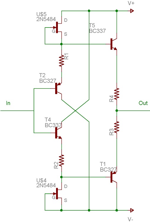
Beneficial, maybe, probably. Cost effective, probably not. Dual opamps tend not to cost much more than single ones. I can see a few changes to that schematic that I am pretty sure would make a bigger difference than what you suggested. First, add resistors in series with the emitters of each of the input transistors in the buffer greater than or equal to the value of the resistors in series with the emitters of the output transistors (>=4.7r), for Class A-AB biasing, and second, replace the 3k biasing resistor for the input transistors of the buffer with a ccs, whether it be a CRD, lone jfet, jfet cascode, or something else. The following is an example of what I mean, though without any parts values. I just happened to have this made up and uploaded to my photobucket account for the Pimeta BUF634 replacement diamond buffer boards I was working on a while ago. To make it a bit easier, you could swap CRDs for the two 2N5484 jfets. It would also remove the need to match the jfets.
discreteDBjfetschAB.png
 
Oct 28, 2006 at 7:02 PM Post #60 of 97
Quote:

Originally Posted by cetoole
Personally, I would just put ps caps from v+ to v-, though you could, and there are arguements for and against this, put caps from v+ to v- and also some from v+ to input gnd and v- to input gnd. Dont put any on the output gnd.


For this amp, since size is a HUGE issue, I'll stick with a single cap between the rails.

Quote:

Originally Posted by cetoole
Beneficial, maybe, probably. Cost effective, probably not. Dual opamps tend not to cost much more than single ones. I can see a few changes to that schematic that I am pretty sure would make a bigger difference than what you suggested. First, add resistors in series with the emitters of each of the input transistors in the buffer greater than or equal to the value of the resistors in series with the emitters of the output transistors (>=4.7r), for Class A-AB biasing, and second, replace the 3k biasing resistor for the input transistors of the buffer with a ccs, whether it be a CRD, lone jfet, jfet cascode, or something else. The following is an example of what I mean, though without any parts values. I just happened to have this made up and uploaded to my photobucket account for the Pimeta BUF634 replacement diamond buffer boards I was working on a while ago. To make it a bit easier, you could swap CRDs for the two 2N5484 jfets. It would also remove the need to match the jfets.
discreteDBjfetschAB.png


As for Dual vs Single, the only main reason is that I have a couple of OPA627s I'm dying to use for this and have tons of TLE2426s lying around.

For the CSS, I'm also building a SOHA so I have ordered a few J113 which I would use for this position.


Thanks for the reply! Since I've got a layout that I hope will work, I'll go start building the original version and see if I can fit it into a Hammond 1455C802 with a DIY tread and a 9V
smily_headphones1.gif
 

Users who are viewing this thread

Back
Top