New DIY Altoids Tin Amp - The Pocket Class A "Wintergreen Handwarmer" by xrk971
May 18, 2017 at 8:27 PM Post #301 of 468
The JFET Drain voltage after the 1k might be too high for this mosfet. That's why I said it need to be simulated to set the D.C. Levels properly. If you have an IRF610 and change to the values shown in my last post - it will work.
 
May 19, 2017 at 3:22 PM Post #302 of 468
I switched to a 160W 18V power supply and the amp powered up OK.

but I only get sound from RIGHT channel, LEFT channel is silent

new DMM readings:

M1A Pins 1 2 3: 11.9v, 18v, 9v
M1B Pins 1 2 3: 10.64v, 18v, 8.8v
Q1A: Pins G D S: 1.97v, 2.25v, 10.6v
Q1B: Pins G D S: 1.9v, 10.9v, 2.1v <--- D and S values seems opposite from Q1A!?
across R3A: 7.4v
across R3B: 7.11v

is the "B" path left channel or right channel? curious how come the JFET values for S and D are reversed between the A channel and B channel.
 
May 19, 2017 at 3:29 PM Post #303 of 468
I switched to a 160W 18V power supply and the amp powered up OK.

but I only get sound from RIGHT channel, LEFT channel is silent

new DMM readings:

M1A Pins 1 2 3: 11.9v, 18v, 9v
M1B Pins 1 2 3: 10.64v, 18v, 8.8v
Q1A: Pins G D S: 1.97v, 2.25v, 10.6v
Q1B: Pins G D S: 1.9v, 10.9v, 2.1v <--- D and S values seems opposite from Q1A!?
across R3A: 7.4v
across R3B: 7.11v

is the "B" path left channel or right channel? curious how come the JFET values for S and D are reversed between the A channel and B channel.
measuring across R7A 8.8v
measuring across R7B 9v
 
May 19, 2017 at 4:46 PM Post #304 of 468
Good news, we are making progress. Did you have a second board with new FETs or did you replace the MOSFETs on first board?

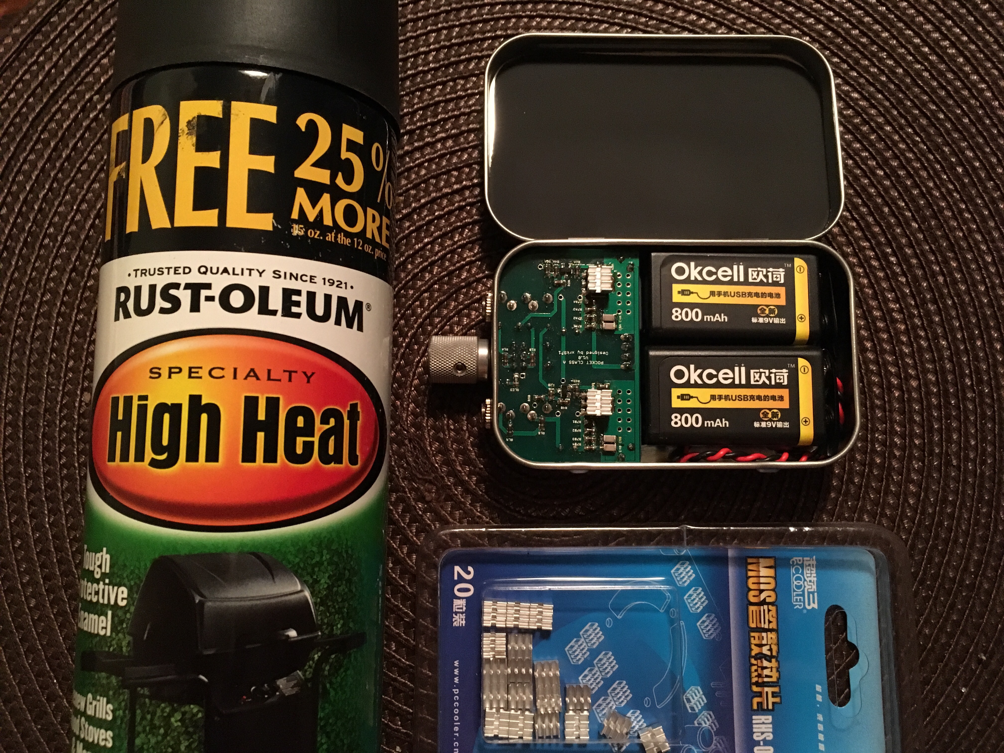
The JFET Q1 and Q2 are laid out in opposite orientation for convenience of routing. This is possible because the JFET is symmetric, that is D & S are interchangeable for the BF862. A very nice feature - it basically works as a gate-controlled variable resistor. So your measurements are right on the mark. From the DC setpoints data, it looks like the amp is fully functional on both channels. Bias current is a bit on high side but ok - at the max allowed thermally (76mA). Your bias currents are actually pretty well matched for both the JFETs and the MOSFETs - it should be an excellent sounding amp.

Why no music out of one channel? Possibly a bad 3.5mm stereo jack connector? I bet, if you take your DMM probe in AC volts mode and touch the S (pin 3) of the MOSFET while playing music loud on the input (assuming input jack pins are good etc), you will see fluctuating AC volts - sign of music.

When the DC setpoints are all good - the amp HAS to WORK! If no music, it is a bad connection somewhere.

These are all excellent values and means the amp should be fully working.

Measurements Show:

M1A Pins 1 2 3: 11.9v, 18v, 9v
M1B Pins 1 2 3: 10.64v, 18v, 8.8v
Q1A: Pins G D S: 1.97v, 2.25v, 10.6v
Q1B: Pins G D S: 1.9v, 10.9v, 2.1v <--- D and S values seems opposite from Q1A!?
across R3A: 7.4v
across R3B: 7.11v
measuring across R7A 8.8v
measuring across R7B 9v
Good luck - you are very close. It is something like a bad cable, bad solder joint, bad jack, bad wire, etc.

A is right channel (look for Ring on 3.5mm jack) and B is left channel (look for tip on 3.5mm jack).
 
Last edited:
May 19, 2017 at 5:16 PM Post #305 of 468
Hi X,

this is still the first board, I soldered on K942 mosfets standing up and got these values, I will touch up the solder points of the jacks and see what happens.

also I will monitor the AC currents through the S legs of mosfets

will report back!
 
May 19, 2017 at 5:25 PM Post #306 of 468
Why no music out of one channel? Possibly a bad 3.5mm stereo jack connector? I bet, if you take your DMM probe in AC volts mode and touch the S (pin 3) of the MOSFET while playing music loud on the input (assuming input jack pins are good etc), you will see fluctuating AC volts - sign of music.

for this AC volts measurement, I touch red probe on MOSFET S pin and where do I touch the black probe?

I get same 9V readings by only using the red probe on MOSFET S pins, and leaving black probe in the air...
 
May 19, 2017 at 5:27 PM Post #307 of 468
for this AC volts measurement, I touch red probe on MOSFET S pin and where do I touch the black probe?

I get same 9V readings by only using the red probe on MOSFET S pins, and leaving black probe in the air...

Unless otherwise specified, you should assume probing a pin means with respect to ground. The voltage at a point/node/pin is generally with respect to ground (black probe on gnd), and the voltage across something is putting one probe on each side of something. You put the red on source and black on gnd and ensure you are getting some AC voltage (with music input, of course)
 
May 19, 2017 at 5:47 PM Post #308 of 468
Unless otherwise specified, you should assume probing a pin means with respect to ground. The voltage at a point/node/pin is generally with respect to ground (black probe on gnd), and the voltage across something is putting one probe on each side of something. You put the red on source and black on gnd and ensure you are getting some AC voltage (with music input, of course)
DMM in AC voltage mode, and in 2V digit reading, with black probe on the GND pin from input jack, I get these readings at following locations:
input jack signal pin closer to edge: 0.068v
input jack signal pin further away from edge: 0.055v
M1A S pin: 0.025v
M1B S pin: 0.014v
output jack signal pin further away from edge: 0.014v
output jack signal pin closer to edge: 0.025v

this is with all volumes (DAP and AMP) at max value.
 
May 19, 2017 at 6:24 PM Post #309 of 468
If you are using your own random mosfet then I can't guarantee it will work even if DC setpoints are sort of within range. It strange that it looks like the output is lower than the input. On the side that plays music, is it loud? 14mV AC should make sound and not be silent. So you may have a short to ground on the output somewhere. This would explain the no sound yet good DC levels. But AC goes to zero. To check for this remove power and set DMM to ohms and measure resistance on output side of C2 and ground. It should be same as RL - about 270ohms pet the schematic. If it is low like a couple ohms or less, you may have an inadvertent solder bridge to ground on the output.
 
May 23, 2017 at 1:04 PM Post #311 of 468
Great work with this amp, can't wait to try it out.

Does changing the distance between components affect audio quality?
For example, i am planning on building an O2 amp (+ODAC) on a custom enclosure (still using the official PCB), and some of the components, namely the input/output jacks, power, buttons/switches, and potentiometer will not be soldered on the PCB, rather they would be connected through wires to it inside the custom case (which obviously will not be used as a portable amp). Will this affect the overall sound quality of the amp?

I apologise if this might highjack the convo a bit, but i lack permissions still to post a new thread here.
Thank you for your attention.
 
May 23, 2017 at 5:24 PM Post #313 of 468
Great work with this amp, can't wait to try it out.

Does changing the distance between components affect audio quality?
For example, i am planning on building an O2 amp (+ODAC) on a custom enclosure (still using the official PCB), and some of the components, namely the input/output jacks, power, buttons/switches, and potentiometer will not be soldered on the PCB, rather they would be connected through wires to it inside the custom case (which obviously will not be used as a portable amp). Will this affect the overall sound quality of the amp?

I apologise if this might highjack the convo a bit, but i lack permissions still to post a new thread here.
Thank you for your attention.

Nah you're good. Just try to avoid having the wires be near the power line
 
May 23, 2017 at 6:54 PM Post #315 of 468
Good day to all! I just have a noob question: Can this amp be used for amping IEMs too? Or is this specifically catered for HPs? Thanks!

It will amp anything with an impedance between 30 and 600 ohms. If you are at the extreme low end of that range, you'll probably want to set the bias high for best dynamics and and put in at least 1000uF per channel for the output caps for bass performance. Otherwise the stock config works great.
 
Last edited:

Users who are viewing this thread

Back
Top