


xrk971
Member of the Trade: XRKAudio
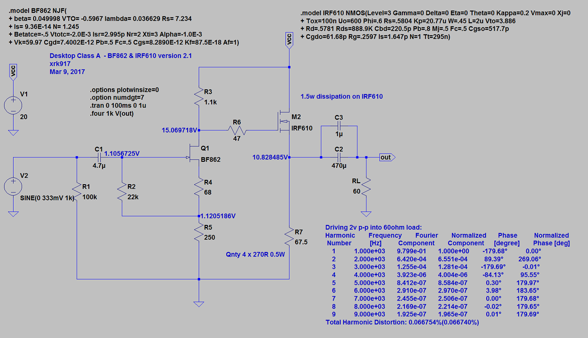
Perhaps JFET is fine and R5 is either failed or has cold solder joint. The attached sim shows a bad R5 (open) gives 14.8v on all pins of JFET and 12v on S of MOSFET.
So check R5's resistance relative to GND, check that it is connected to R4, and check to see if it is connected to GND on one end.

So check R5's resistance relative to GND, check that it is connected to R4, and check to see if it is connected to GND on one end.

Last edited: