


hakuzen
Headphoneus Supremus
- Joined
- Feb 9, 2016
- Posts
- 1,806
- Likes
- 2,682
thank you very much and forgive my total ignorance.
i'm going to start reading from all your links, thanks!
i'm going to start reading from all your links, thanks!

PS: @Chris I keep on half derailing the topic because you have such a tidy and up to date first page. and understanding what happens IMO goes with understanding how to do those measurements which was one of your goals. but it's your topic, if you wish to keep it clean with only measurements and FR talks, just say so and I can remove what you don't want here.


Speaking of that, I should really finally get around measuring my Nexus 7 2nd generation tablet but am too lazy to load the RMAA test file on it. I haven't even ever connected a headphone to it yet, at least not to my knowledge.
Its predecessor had a horribly high output impedance.
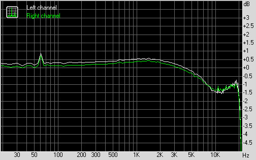
Xiaomi RedMi Note 2
unloaded and loaded (Pai Audio MR3) (note different scale): same, activating Mi Sound Enhancer (for general in-ear):


It would be great if you could report the output impedance, though you need resistors.
I don't wish to be unthankful, because I do appreciate the effort taken in order to measure the different devices. This is very helpful.
But there seems to be a discrepancy between your measurements of the Chord Mojo and measurements from Stereophile Ohm Image:
http://www.stereophile.com/content/chord-electronics-mojo-da-headphone-amplifier-measurements#h1qZF5tVfa55H9kL.97
http://ohm-image.net/data/audio/rmaa-chord-mojo-24-bit
How come? Because the difference is quite significant.

