


SanjiWatsuki
500+ Head-Fier
- Joined
- Oct 21, 2011
- Posts
- 716
- Likes
- 106
I've been recently thinking about the nature of headphone modding and how to properly attack it from a sound science perspective, rather than trial and error. I'm not an extremely experienced headphone modder, nor am I an audio engineer, but I'm looking for criticism of my headphone modding breakdown. This is just a collection of my speculations with sources.
My analysis is focused on closed-back headphone modding, although some of the concepts apply to open-back headphone modding.
It seems to me like most headphone mods come down to several forms:
1. Acoustic filter removal, or (less commonly) adding.
Most fabrics and types of paper seem to absorb certain frequency ranges. This is why you commonly see felt or other fabrics covering the driver. Sometimes, these fabrics are in the design for dust filter and protection reasons, other times it is to attenuate the sound.
An acoustic filter, in this case, is defined as anything on the ear-side part of the driver such that it blocks the path of the sound coming from the driver from directly entering the ear. Because the acoustic filter, generally speaking, absorbs higher frequencies better than it does lower frequencies, this almost always has the effect of reducing the treble.
As shown by Arnaud [0] and through experimentation, the thicker the acoustic filter, the greater the attenuation.
I hypothesis that, as a generalization, removal of an acoustic filter will increase the treble (more so the higher the frequency goes) and the opposite can be expected for the addition of an acoustic filter. It appears that the absorption of a lot of common filtering materials is going to start in the lower mids and continue to increase into the upper treble. I believe this treble boost is why people believe they often see a clarity increase as a result of removing an acoustic filter -- it's increased treble or extra "detail" in many cases.
2. Effective cavity size.
I believe this is a function of two parts. The first part is the raw function of filling the headphone cup cavity. Given that the speed of sound in air is roughly 343m/s, we can roughly estimate the wave length of a given frequency range. That is to say, if the length of the cavity matches the wave length of the sound wave, we should expect a resonance. Resonances appear in the frequency response as peaks preceded by a dip. This is a complete estimate and should not be expected to truly match the real resonance -- you'd need modeling software to truly figure this out as even lumped analysis struggles past 1khz.
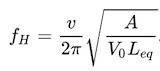
We can estimate the resonant frequency of the headphone cup by measuring its depth and diameter and modeling it as a cylinder. In most situations, we are modding a closed-back headphone, so we will model it as an open-closed cylinder. The resonant frequency can be estimated using the formula f = (harmonic #) * (speed of sound) / (4 * ((depth of headphone in m) + 0.4 * (diameter of headphone cup in m)).
Thus, given a hypothetical headphone of 0.7cm depth and a 3cm diameter. Our estimated harmonic frequency will be f = 343 / (4 * (0.007 + 0.03 * .4))) = 4513hz. This matches pretty close to the ATH-M50 measurements’ resonance at InnerFidelity, interestingly, suggesting that we’re in the ball park on our resonance calcs [1].
Therefore, direct cavity stuffing can be interpreted as a function of reducing internal cup size. When you reduce internal cup size, you increase the internal resonance frequency (because the divisor drops), moving your dip further away into the higher frequencies.
Loose fitting of teased cotton balls or polyfill, however, INCREASES the effective cavity size. This is a known phenomenon in subwoofer fillers to "trick" the subwoofer into thinking it is in a larger enclosure [2]. In subwoofers, regardless of a ported or sealed sub, the effective size increases with certain densities of polyfill, changing the resonant frequency. Arnaud's calculations from [0] suggest that, theoretically, one can double the effective headphone cup size with the proper application of polyfill. This effect is also attenuated by the treble absorbing capabilities of the fibers, however.
[0] also notes the reduced compliance of the air when the cup size is reduced (or when ports are closed on a closed pair of headphones). In practice, this seems to show up as a reduction of the mid-bass frequencies and an increase in the sub-bass frequencies, going off T50RP data from the BMF thread. For example, the Acoustipack and felt mod measurements show this phenomenon going on [4].
Putting it all together, my hypothesis is that stuffing a headphone enclosure increases the resonant frequency of the housing, causing higher frequency resonances with greater amplitudes of the peaks. Very lightly filling the cavity with a polyfill material will reduce the resonant frequency but will also likely attenuate the treble frequencies to some degree.
2a. Figuring out resonant frequencies from more reliable means.
The model listed above is a very rough estimation and is not suggested if further measurements are available. Resonant frequencies appear on impedance graphs as blips for dynamic headphones [5]. These are not necessarily resonances due to the cavity size, but a resonance nonetheless. For this reason, we can look at the M50 graph again and see that there is a blip at around 4khz, which shows up as the valley and peak in the frequency response.
3. Mass loading
In T50RP modding, plasticine is a commonly used material to "mass load" the enclosure. It's origin appears to be speaker modding where weight is added to the base of a speaker to fine tune it [3]. In subwoofers, it is a form of resonance control to avoid losing energy to the cabinet itself rocking back and forth. The use of commercial roofing material and dynamat on headphones also appears to be a form of mass loading.
I could be wrong, but it seems to me like the amount of energy in the sound wave coming off the back wave of the driver would be insignificant compared to the mechanical energy contained in the driver itself. Logically, it seems to me like mass damping the mechanical vibrations off the driver housing is a lower hanging fruit than mechanical vibrations caused by the back wave. You can see this in such mods at the MarkL mods of the Denon DX000 series.
Given that many high end headphones are quite light (barring orthos which require a massive amount of magnets to make their drivers work), I don't think that mechanical vibrations are an issue in most cases at normal listening volumes. That said, I can't see how this would really hurt the sound quality unless it moved a resonance to some oddball location.
To prove my point, compare the overlay of a mass-damped mod compared with a non-mass-damped mod [12]. The FRs are so close that you could chalk up the differences between them to the differences just between measurements.
4. Back wave damping mechanisms
Most damping mechanisms revolve around damping the back wave of the headphone in some way. Not counting the mass loading variant using dynamat-type materials, this often involves materials like Creatology felt and acoustic foam. Given this [5] by arnaud, we can probably estimate that most materials used to absorb back waves probably follow similar curves when applied very thinly. arnaud also notes that the absorption goes DOWN as the cavity as filled as discussed in #2. Thus, back wave damping seems to often cross over into section 2 with cavity size.
An example of back wave damping is [4] where I have overlaid BMF's incremental stock T50RP (blue) vs. T50RP + Acoustipack and felt (green). I level matched the graphs at 1khz. One way to look at it is that the bass frequencies are all increased -- the alternate way to look at it is that all frequencies above 300hz are shelved. I believe the lower bass effects are resultant from the reduced air compliance causing the lower bass frequencies to rise and the mid-bass to sink.
Damping the rear of the driver appears to have an almost identical effect to damping the back wave in the ear of the cup [11]. This gives the interesting implication that a modder can achieve very similar effects to putting acoustic foam in the rear of the cup by just damping the rear of the driver itself. This can possibly allow for damping of the back wave while using less damping material, allowing for the usage of less materials and filling less volume.
4a. Front wave damping mechanisms
These are more rare as most headphones don’t really allow for it. In the case of headphones like the Sennheiser HD800, however, the driver is positioned far back and angled in the housing. This means that the front wave creates certain SPL hot spots on the inside of the headphone itself [1]. This can be damped to reduce the treble coming off the front wave and is the basis of most HD800 mods. Generally speaking, the maximum return on this is about -3dB attenuation of the treble [10].
A sub-type of the front wave damping is the damping of the front wave off the face. This appears in mods like the Jerg Fuzzor mod [9]. Because this is damping a reflection of a reflection, I would expect diminishing returns.
5. Headphone Pad Effects
There is a huge effect from rolling headphone pads. There are people vouching everything about this. The exact effects are still pretty elusive as there is not that much measurement data for pad rolling, and because pads can differ so much.
The rule of thumb seems to be that you get more bass the less compliant your headphone pads are (or less mids and treble, depending on how you look at it). That is to say, gel pads will have very high amounts of bass, leather/pleather pads will have more than velour pads, and also more bass with greater clamp (squished headphone pads == less complaint headphone pads) [6]. Mods like the “white caulk mod” where rope caulk is used to adhere a headphone pad to the headphone can be used to reduce air leakage on headphones where the pads are not fitting properly (i.e. trying to fit something like an FA-003 pad on a T50RP).
6. Bass Vent Tuning
Many closed-back headphones have bass vents in some way. The HD202 has them in a little spot on the center of the cup. The Sony MDR1R has them on the baffle [7]. The T50RP has them directly on the face of the cups. In all cases, covering or uncovering these vents causes massive changes to the bass response. Covering them up typically reduces the bass and changes the bass balance -- uncovering them unleashes the bass.
Theoretically, it seems like opening the bass vent allows for air in the back wave to exit from the headphone cup. This alters the compliance of the air behind the driver. Covering the vent decreases the air compliance, causing similar acoustic effects to the bass as a smaller cup size would entail. It appears that this has diminishing returns as, past a certain point, the bass instead begins to decreases as the headphone is opened more.
An example of a comparison between lightly damped and a sealed bass vent is shown by [8], an overlay of two measurements from the BMF T50RP thread. The decreased air compliance has resulted in a significant decrease in frequencies below 300hz, centered on the mid-bass, but also significantly reducing the sub-bass. As a generalization, we can suggest that sealing the bass vents appears to affect the mid-bass more significantly than the sub-bass, just as when we decreased air compliance via cup volume. Rin Choi’s measurements seem to suggest that, as vents are progressively more blocked, a peak begins to form at 1khz making it closer to a low pass filter.
7. Electrical Mods
The simplest of these mods is simply putting a resistor in the cable. Etymotics does this commercially with a 120 ohm resistor to “convert” an IEM into another. Speaking generally, adding a resistor to the cable increases the frequencies like the impedance chart looks -- peaks at certain frequencies turn into an increase at those frequencies.
Typically, this results in an increase in mid-bass as there is often a mid-bass resonance from the compliance of the headphone pads, referred to as “springiness” in the InnerFidelity article [5].
More advanced, users like Solderdude design passive circuits that essentially act as equalizers for the headphone. These can be specialized to fix a frequency response for a particular headphone or headphone mod. This has the downside of causing unintentional FR shifts when used with high impedance sources.
8. Driver Transplant
Moving the driver to a new housing will, of course, change the sound very significantly. Due to the massive variance in these types of mods, it’s hard to analyze.
[0] http://www.head-fi.org/t/452404/just-listened-to-some-fostex-t50rps-today-wow/2925#post_7784890
[1] http://www.innerfidelity.com/images/AudioTechnicaATHM50B2012.pdf
[2] http://www.moodym.com/audio/fiber.html
[3] http://www.monitoraudio.co.uk/support/glossary/
[4] http://i.imgur.com/1xtIeRU.png
[5] http://www.innerfidelity.com/content/skullcandys-director-electrical-acoustical-engineering-dr-tetsuro-oishi-visits-innerfidelit-0
[6] http://usir.salford.ac.uk/27397/
[7] http://rinchoi.blogspot.com/2013/08/on-modification-of-sony-mdr-1r-its-as.html
[8] http://i.imgur.com/R7YN1U5.png
[9] http://www.head-fi.org/t/692494/hifiman-fuzzor-mod-driver-backwave-felt-damping-modification
[10] http://www.head-fi.org/t/589738/sennheiser-hd-700-officially-unveiled-at-ces-2012/2985#post_8427494
[11] http://i.imgur.com/qEzt9Tf.png
[12] http://i.imgur.com/8CbjSRT.png
My analysis is focused on closed-back headphone modding, although some of the concepts apply to open-back headphone modding.
It seems to me like most headphone mods come down to several forms:
1. Acoustic filter removal, or (less commonly) adding.
Most fabrics and types of paper seem to absorb certain frequency ranges. This is why you commonly see felt or other fabrics covering the driver. Sometimes, these fabrics are in the design for dust filter and protection reasons, other times it is to attenuate the sound.
An acoustic filter, in this case, is defined as anything on the ear-side part of the driver such that it blocks the path of the sound coming from the driver from directly entering the ear. Because the acoustic filter, generally speaking, absorbs higher frequencies better than it does lower frequencies, this almost always has the effect of reducing the treble.
As shown by Arnaud [0] and through experimentation, the thicker the acoustic filter, the greater the attenuation.
I hypothesis that, as a generalization, removal of an acoustic filter will increase the treble (more so the higher the frequency goes) and the opposite can be expected for the addition of an acoustic filter. It appears that the absorption of a lot of common filtering materials is going to start in the lower mids and continue to increase into the upper treble. I believe this treble boost is why people believe they often see a clarity increase as a result of removing an acoustic filter -- it's increased treble or extra "detail" in many cases.
2. Effective cavity size.
I believe this is a function of two parts. The first part is the raw function of filling the headphone cup cavity. Given that the speed of sound in air is roughly 343m/s, we can roughly estimate the wave length of a given frequency range. That is to say, if the length of the cavity matches the wave length of the sound wave, we should expect a resonance. Resonances appear in the frequency response as peaks preceded by a dip. This is a complete estimate and should not be expected to truly match the real resonance -- you'd need modeling software to truly figure this out as even lumped analysis struggles past 1khz.
We can estimate the resonant frequency of the headphone cup by measuring its depth and diameter and modeling it as a cylinder. In most situations, we are modding a closed-back headphone, so we will model it as an open-closed cylinder. The resonant frequency can be estimated using the formula f = (harmonic #) * (speed of sound) / (4 * ((depth of headphone in m) + 0.4 * (diameter of headphone cup in m)).
Thus, given a hypothetical headphone of 0.7cm depth and a 3cm diameter. Our estimated harmonic frequency will be f = 343 / (4 * (0.007 + 0.03 * .4))) = 4513hz. This matches pretty close to the ATH-M50 measurements’ resonance at InnerFidelity, interestingly, suggesting that we’re in the ball park on our resonance calcs [1].
Therefore, direct cavity stuffing can be interpreted as a function of reducing internal cup size. When you reduce internal cup size, you increase the internal resonance frequency (because the divisor drops), moving your dip further away into the higher frequencies.
Loose fitting of teased cotton balls or polyfill, however, INCREASES the effective cavity size. This is a known phenomenon in subwoofer fillers to "trick" the subwoofer into thinking it is in a larger enclosure [2]. In subwoofers, regardless of a ported or sealed sub, the effective size increases with certain densities of polyfill, changing the resonant frequency. Arnaud's calculations from [0] suggest that, theoretically, one can double the effective headphone cup size with the proper application of polyfill. This effect is also attenuated by the treble absorbing capabilities of the fibers, however.
[0] also notes the reduced compliance of the air when the cup size is reduced (or when ports are closed on a closed pair of headphones). In practice, this seems to show up as a reduction of the mid-bass frequencies and an increase in the sub-bass frequencies, going off T50RP data from the BMF thread. For example, the Acoustipack and felt mod measurements show this phenomenon going on [4].
Putting it all together, my hypothesis is that stuffing a headphone enclosure increases the resonant frequency of the housing, causing higher frequency resonances with greater amplitudes of the peaks. Very lightly filling the cavity with a polyfill material will reduce the resonant frequency but will also likely attenuate the treble frequencies to some degree.
2a. Figuring out resonant frequencies from more reliable means.
The model listed above is a very rough estimation and is not suggested if further measurements are available. Resonant frequencies appear on impedance graphs as blips for dynamic headphones [5]. These are not necessarily resonances due to the cavity size, but a resonance nonetheless. For this reason, we can look at the M50 graph again and see that there is a blip at around 4khz, which shows up as the valley and peak in the frequency response.
3. Mass loading
In T50RP modding, plasticine is a commonly used material to "mass load" the enclosure. It's origin appears to be speaker modding where weight is added to the base of a speaker to fine tune it [3]. In subwoofers, it is a form of resonance control to avoid losing energy to the cabinet itself rocking back and forth. The use of commercial roofing material and dynamat on headphones also appears to be a form of mass loading.
I could be wrong, but it seems to me like the amount of energy in the sound wave coming off the back wave of the driver would be insignificant compared to the mechanical energy contained in the driver itself. Logically, it seems to me like mass damping the mechanical vibrations off the driver housing is a lower hanging fruit than mechanical vibrations caused by the back wave. You can see this in such mods at the MarkL mods of the Denon DX000 series.
Given that many high end headphones are quite light (barring orthos which require a massive amount of magnets to make their drivers work), I don't think that mechanical vibrations are an issue in most cases at normal listening volumes. That said, I can't see how this would really hurt the sound quality unless it moved a resonance to some oddball location.
To prove my point, compare the overlay of a mass-damped mod compared with a non-mass-damped mod [12]. The FRs are so close that you could chalk up the differences between them to the differences just between measurements.
4. Back wave damping mechanisms
Most damping mechanisms revolve around damping the back wave of the headphone in some way. Not counting the mass loading variant using dynamat-type materials, this often involves materials like Creatology felt and acoustic foam. Given this [5] by arnaud, we can probably estimate that most materials used to absorb back waves probably follow similar curves when applied very thinly. arnaud also notes that the absorption goes DOWN as the cavity as filled as discussed in #2. Thus, back wave damping seems to often cross over into section 2 with cavity size.
An example of back wave damping is [4] where I have overlaid BMF's incremental stock T50RP (blue) vs. T50RP + Acoustipack and felt (green). I level matched the graphs at 1khz. One way to look at it is that the bass frequencies are all increased -- the alternate way to look at it is that all frequencies above 300hz are shelved. I believe the lower bass effects are resultant from the reduced air compliance causing the lower bass frequencies to rise and the mid-bass to sink.
Damping the rear of the driver appears to have an almost identical effect to damping the back wave in the ear of the cup [11]. This gives the interesting implication that a modder can achieve very similar effects to putting acoustic foam in the rear of the cup by just damping the rear of the driver itself. This can possibly allow for damping of the back wave while using less damping material, allowing for the usage of less materials and filling less volume.
4a. Front wave damping mechanisms
These are more rare as most headphones don’t really allow for it. In the case of headphones like the Sennheiser HD800, however, the driver is positioned far back and angled in the housing. This means that the front wave creates certain SPL hot spots on the inside of the headphone itself [1]. This can be damped to reduce the treble coming off the front wave and is the basis of most HD800 mods. Generally speaking, the maximum return on this is about -3dB attenuation of the treble [10].
A sub-type of the front wave damping is the damping of the front wave off the face. This appears in mods like the Jerg Fuzzor mod [9]. Because this is damping a reflection of a reflection, I would expect diminishing returns.
5. Headphone Pad Effects
There is a huge effect from rolling headphone pads. There are people vouching everything about this. The exact effects are still pretty elusive as there is not that much measurement data for pad rolling, and because pads can differ so much.
The rule of thumb seems to be that you get more bass the less compliant your headphone pads are (or less mids and treble, depending on how you look at it). That is to say, gel pads will have very high amounts of bass, leather/pleather pads will have more than velour pads, and also more bass with greater clamp (squished headphone pads == less complaint headphone pads) [6]. Mods like the “white caulk mod” where rope caulk is used to adhere a headphone pad to the headphone can be used to reduce air leakage on headphones where the pads are not fitting properly (i.e. trying to fit something like an FA-003 pad on a T50RP).
6. Bass Vent Tuning
Many closed-back headphones have bass vents in some way. The HD202 has them in a little spot on the center of the cup. The Sony MDR1R has them on the baffle [7]. The T50RP has them directly on the face of the cups. In all cases, covering or uncovering these vents causes massive changes to the bass response. Covering them up typically reduces the bass and changes the bass balance -- uncovering them unleashes the bass.
Theoretically, it seems like opening the bass vent allows for air in the back wave to exit from the headphone cup. This alters the compliance of the air behind the driver. Covering the vent decreases the air compliance, causing similar acoustic effects to the bass as a smaller cup size would entail. It appears that this has diminishing returns as, past a certain point, the bass instead begins to decreases as the headphone is opened more.
An example of a comparison between lightly damped and a sealed bass vent is shown by [8], an overlay of two measurements from the BMF T50RP thread. The decreased air compliance has resulted in a significant decrease in frequencies below 300hz, centered on the mid-bass, but also significantly reducing the sub-bass. As a generalization, we can suggest that sealing the bass vents appears to affect the mid-bass more significantly than the sub-bass, just as when we decreased air compliance via cup volume. Rin Choi’s measurements seem to suggest that, as vents are progressively more blocked, a peak begins to form at 1khz making it closer to a low pass filter.
7. Electrical Mods
The simplest of these mods is simply putting a resistor in the cable. Etymotics does this commercially with a 120 ohm resistor to “convert” an IEM into another. Speaking generally, adding a resistor to the cable increases the frequencies like the impedance chart looks -- peaks at certain frequencies turn into an increase at those frequencies.
Typically, this results in an increase in mid-bass as there is often a mid-bass resonance from the compliance of the headphone pads, referred to as “springiness” in the InnerFidelity article [5].
More advanced, users like Solderdude design passive circuits that essentially act as equalizers for the headphone. These can be specialized to fix a frequency response for a particular headphone or headphone mod. This has the downside of causing unintentional FR shifts when used with high impedance sources.
8. Driver Transplant
Moving the driver to a new housing will, of course, change the sound very significantly. Due to the massive variance in these types of mods, it’s hard to analyze.
[0] http://www.head-fi.org/t/452404/just-listened-to-some-fostex-t50rps-today-wow/2925#post_7784890
[1] http://www.innerfidelity.com/images/AudioTechnicaATHM50B2012.pdf
[2] http://www.moodym.com/audio/fiber.html
[3] http://www.monitoraudio.co.uk/support/glossary/
[4] http://i.imgur.com/1xtIeRU.png
[5] http://www.innerfidelity.com/content/skullcandys-director-electrical-acoustical-engineering-dr-tetsuro-oishi-visits-innerfidelit-0
[6] http://usir.salford.ac.uk/27397/
[7] http://rinchoi.blogspot.com/2013/08/on-modification-of-sony-mdr-1r-its-as.html
[8] http://i.imgur.com/R7YN1U5.png
[9] http://www.head-fi.org/t/692494/hifiman-fuzzor-mod-driver-backwave-felt-damping-modification
[10] http://www.head-fi.org/t/589738/sennheiser-hd-700-officially-unveiled-at-ces-2012/2985#post_8427494
[11] http://i.imgur.com/qEzt9Tf.png
[12] http://i.imgur.com/8CbjSRT.png

