SOHA II Builders Thread
Nov 22, 2008 at 2:41 AM Post #166 of 1,694
I was. But we can wait another day.
smily_headphones1.gif
 
Nov 22, 2008 at 4:00 PM Post #167 of 1,694
Oh dear! smoke! not a good start
frown.gif


D3P and D4P are toast! I've pulled them both from the board and the plated hole of D4P is completely burnt as is the trace from D3P to D4P.

I'm sure they were installed correctly with the banded end uppermost and I've checked the remaining vertically mounted diodes and they're all installed the same way.

I've just verified all the PS capacitors are installed with correct polarity.

J1,2 & 3 were not strapped so it's nothing downstream from the PS would be causing it.

any ideas why?
 
Nov 22, 2008 at 6:11 PM Post #169 of 1,694
Ferrari,

An L7915CV is installed at LV- with an L7815CV at LV+

could it be anything to do with how they're mounted onto the heatsinks?

I've used silpad400 insulated adhesive thermal pads between device and heatsink and the securing bolt has a metal washer and plastic insulator on the the device side, with a spring washer and nut on the other side. I can't take pictures atm so I hope that explains it clearly enough.
 
Nov 22, 2008 at 6:38 PM Post #170 of 1,694
Can you measure the continuity between the metal tab on the regulators and the heatsinks?

If these are all open circuit, then it's hard to know what might be wrong.

The only next step that I can think of (if you're sure diodes and caps are oriented correctly) is to pull the regulators, reinstall D3 and D4 and fire it up to see what you get on the various filter caps.

Also, please check the transformer wiring to make sure that it is 15-0-15 properly phased.
 
Nov 22, 2008 at 9:50 PM Post #171 of 1,694
Thoughts about using a 6N30/6H30 in the II? Possible? I checked the pinouts against the 6Dj8, but I think the filament current is around 800mA - correct?
 
Nov 22, 2008 at 11:25 PM Post #172 of 1,694
Quote:

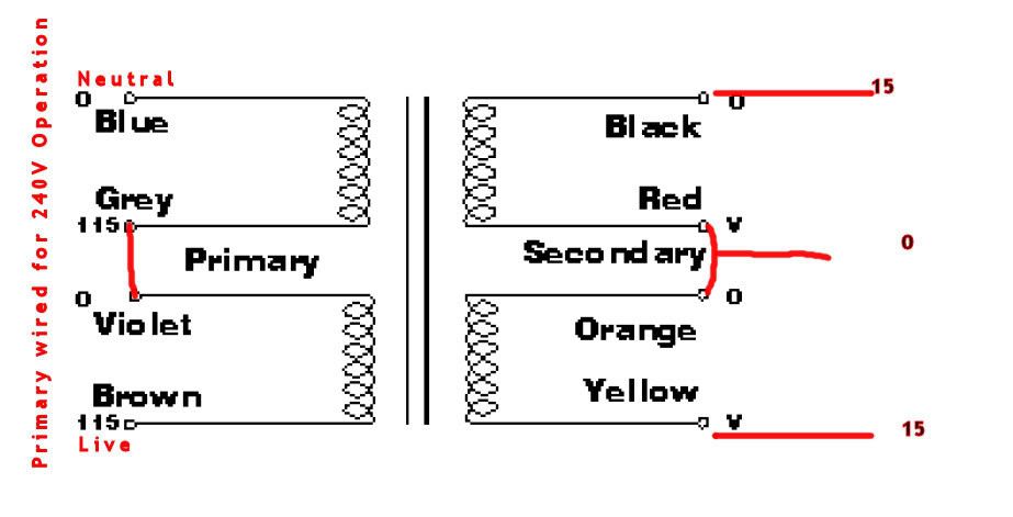
Originally Posted by runeight /img/forum/go_quote.gif
Can you measure the continuity between the metal tab on the regulators and the heatsinks?

If these are all open circuit, then it's hard to know what might be wrong.

The only next step that I can think of (if you're sure diodes and caps are oriented correctly) is to pull the regulators, reinstall D3 and D4 and fire it up to see what you get on the various filter caps.

Also, please check the transformer wiring to make sure that it is 15-0-15 properly phased.


I dont get any continuity between the metal tab and the heatsink body but I was getting continuity between the tab and the bolt which concerned me.

Some shots of the board after the burn out

001.jpg


002.jpg


003.jpg


004.jpg


I've managed to remove the regulators but it was a struggle and some of the caps had a bit of charge in them even after I tried using a bleed resistor as suggested. I ended up cutting the legs off the regulators and then removing the remainder of the legs from the pcb. Some of the pads are looking in quite a sorry state now
frown.gif


I won't have time to do anything more on it tomorrow due to prior commitments and, in any case, I have to order some more regulators.

will keep you updated, but if anyone has any helpful comments in the meantime, please let me know.
 
Nov 23, 2008 at 12:48 AM Post #173 of 1,694
Quote:

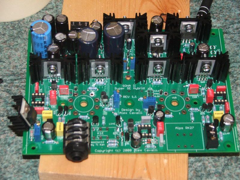
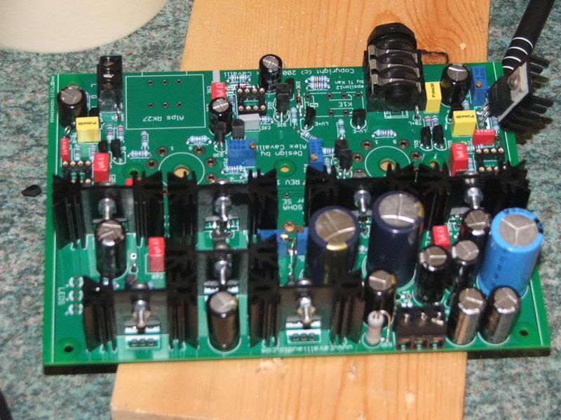
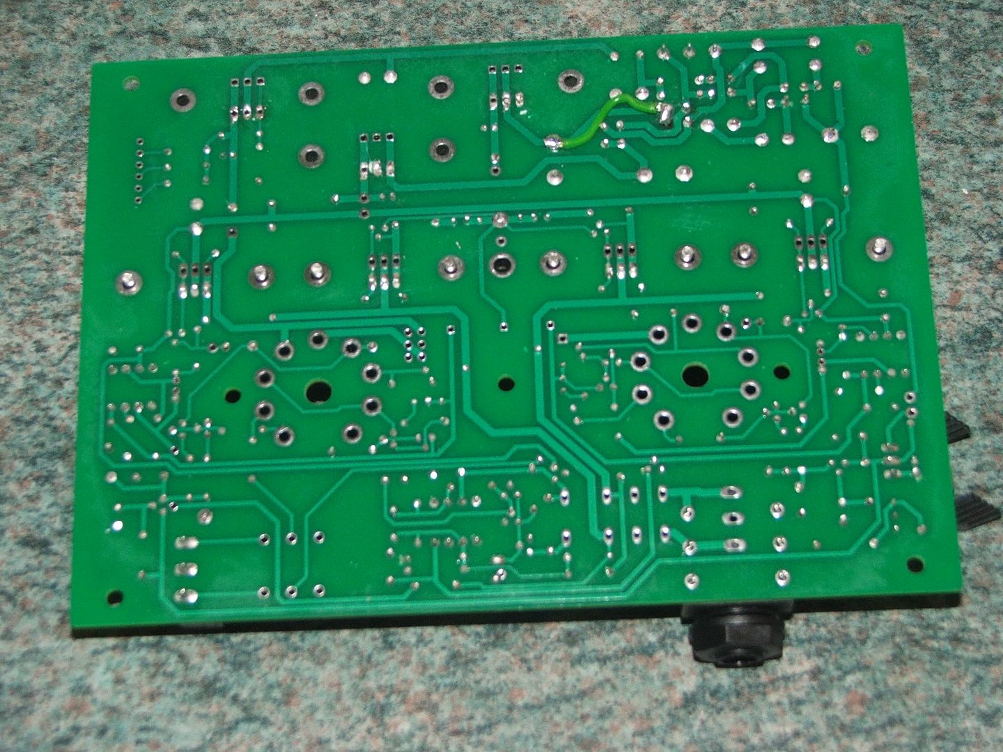
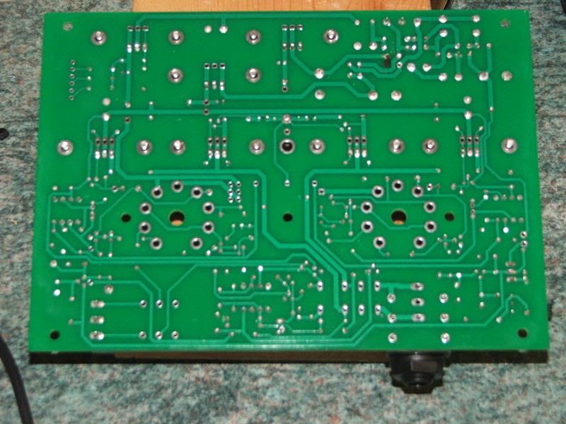
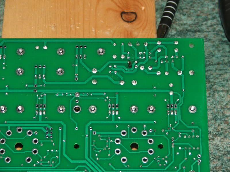
Originally Posted by Uncle Bob /img/forum/go_quote.gif
I dont get any continuity between the metal tab and the heatsink body but I was getting continuity between the tab and the bolt which concerned me.


Did you measure to the black heatsink surface or the bare leg going through the PCB? The black anodised surface may not be very conductive, but the bolt may have scratched it.
 
Nov 23, 2008 at 2:49 AM Post #174 of 1,694
Uncle Bob the next step, now that all of the regs are out, is to replace D3 and D4 and repair the evaporated trace (if possible). Then fire up the PS and measure the voltages across C3P, C4P, and C6P.

If the amp blows up with no regs there is something very wrong in the basic rectifier filter section. It will be a challenge to find it, but I'm pretty sure that we can.

If all voltages are normal and if you don't get explosions, then we replace the regulators one by one starting with the heater regulator.

This is the only way I can think of to try to isolate the problem to a specific portion of the circuit.

Also, one small housekeeping detail for when you case it up. You don't need a heatsink on the HV+ regulator. It won't get very hot and this will save you some space.
 
Nov 23, 2008 at 11:04 AM Post #175 of 1,694
Quote:

Originally Posted by runeight /img/forum/go_quote.gif
Also, please check the transformer wiring to make sure that it is 15-0-15 properly phased.


This is how I had the transformer wired, can you confirm this is correct?

torroidwiring.jpg
 
Nov 23, 2008 at 8:30 PM Post #177 of 1,694
Quote:

Originally Posted by wiatrob /img/forum/go_quote.gif
Thoughts about using a 6N30/6H30 in the II? Possible? I checked the pinouts against the 6Dj8, but I think the filament current is around 800mA - correct?


Unless the pin compatibility with the other SOHA II tubes, I think that the 6N30P-EB (or 6N30P-DR) is an exception since the heater current requirement of this tube is a bridge too far for the LM337 regulator. The LM337 maximum current rating is 1.5A while the current requirement of 2 6N30P tubes is ~1.6A (on average).

Other regulators like LM350 (3A) or LM338 (5A) can handle much more current but it requires a re-design of the heater circuit section, with the associated complications.
smily_headphones1.gif
 
Nov 24, 2008 at 8:49 PM Post #179 of 1,694
the trace you repaired with green wire, follow it left, is there a component in there? if so looks like a bad joint. If not then apologies.
 

Users who are viewing this thread

Back
Top