Post pics of your solder joints: reference thread for DIYs
Mar 29, 2005 at 6:45 PM Post #16 of 77
Quote:

Originally Posted by headchange4u
Here's a pic of a corretly soldered LPC pin header on a XBox motherboard (version 1.5). Notice how the solder forms a cone shape.


Actually, no, that's too much solder, and you don't have full wetting on a few of the pins, the rightmost pin being the most obvious. The solder should form a smooth concave curve from the pin right to edge of the pad. Instead, you have convex curves that do not have full contact with the pad. Acceptable for consumer electronics, but it will be rejected for medical, automotive, telecommunications, and aerospace/military applications.

Ideally you want a solder joint that looks like the one on the right in the picture below. The solder forms a smooth concave curve and tapers down to nothing at the edge of the pad, full coverage, full wetting.
solderrca2.jpg


Here's a cross-section view of what you should be aiming for.

betterfig5.jpg


As a general note, guys, go easy on the solder, you don't need that much.
 
Mar 29, 2005 at 7:05 PM Post #18 of 77
Quote:

Originally Posted by aerius
Actually, no, that's too much solder, and you don't have full wetting on a few of the pins, the rightmost pin being the most obvious. The solder should form a smooth concave curve from the pin right to edge of the pad. Instead, you have convex curves that do not have full contact with the pad. Acceptable for consumer electronics, but it will be rejected for medical, automotive, telecommunications, and aerospace/military applications.


The pic above is a reference pic from the teamxecuter.com web site. I have completed about 25-30 Xbox mods and all my solder joints look the same. I think the lack of the "concave" it may have something to do with the size and shape of the header pins (they are square not round). It may look like a lot of solder but you need to realize how small the pin header is. The whole LPC header section is not much wider than my thumbnail. I wish I had a camera that took good close-up pics so I could show you some of mine.
 
Mar 29, 2005 at 7:32 PM Post #21 of 77
RnB180

I can't see any post knocking your soldering, in fact one of your connections is used as an example of a good concave solder!

Did I miss something?
eek.gif


Whoops brain said concave - fingers typed convex
 
Mar 29, 2005 at 7:35 PM Post #22 of 77
Quote:

Originally Posted by RnB180
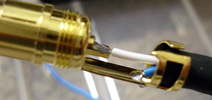
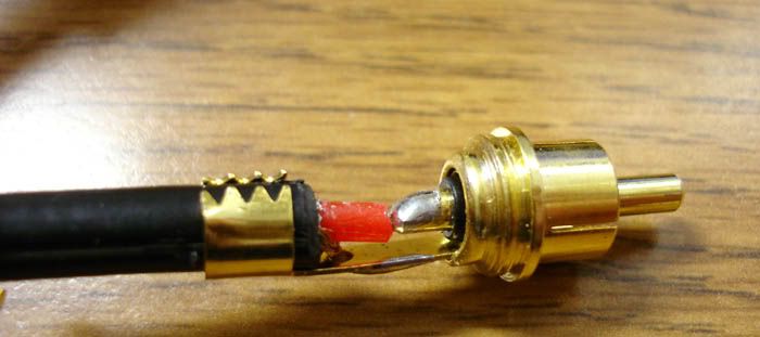
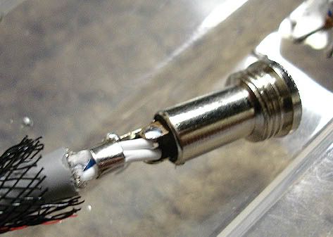
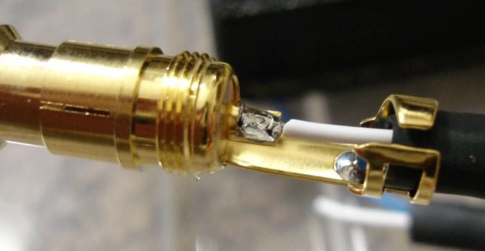
if you think thats too much solder, man.. than you need to check out how to solder the ground on Cardas RCA and WBT RCA connectors. anyone care to show us a pic of the ground joint
smily_headphones1.gif


I think there's been a slight misunderstanding somewhere. What I'm trying to say is the ground on that particular plug of yours is perfect, and that's what we should all be aiming for. You do good work, better than what I've seen on a lot of stuff, and I agree that the centre pin on RCA jacks needs more solder than normal.

Quote:

Originally Posted by headchange4u
The pic above is a reference pic from the teamxecuter.com web site. I have completed about 25-30 Xbox mods and all my solder joints look the same. I think the lack of the "concave" it may have something to do with the size and shape of the header pins (they are square not round). It may look like a lot of solder but you need to realize how small the pin header is. The whole LPC header section is not much wider than my thumbnail. I wish I had a camera that took good close-up pics so I could show you some of mine.


I know that small joints are not as forgiving and easy to do as larger ones. They don't wet as nicely and solder behaves funny when the parts get small enough. I've soldered stuff that small before and I know it's not nearly as easy as the stuff found in typical DIY projects, but you can get smooth, concave joints with practice. What it looks like to me is that you're not getting good contact with the pad with the soldering iron tip. The solder tends to stick to the pin which is hotter and doesn't wet onto the pad as well as it should.


BTW, if I sound picky it's because I used to build & test automotive airbag modules at one of my jobs. Those things have to work 100% of the time and are not allowed to fail.
 
Mar 30, 2005 at 9:23 PM Post #28 of 77
E5DD9020_filtered.jpg


my k1k chipamp
 

Users who are viewing this thread

Back
Top