Just listened to some Fostex T50RPs today... WOW!
Aug 31, 2013 at 11:49 AM Post #10,366 of 11,346
Quote:
 
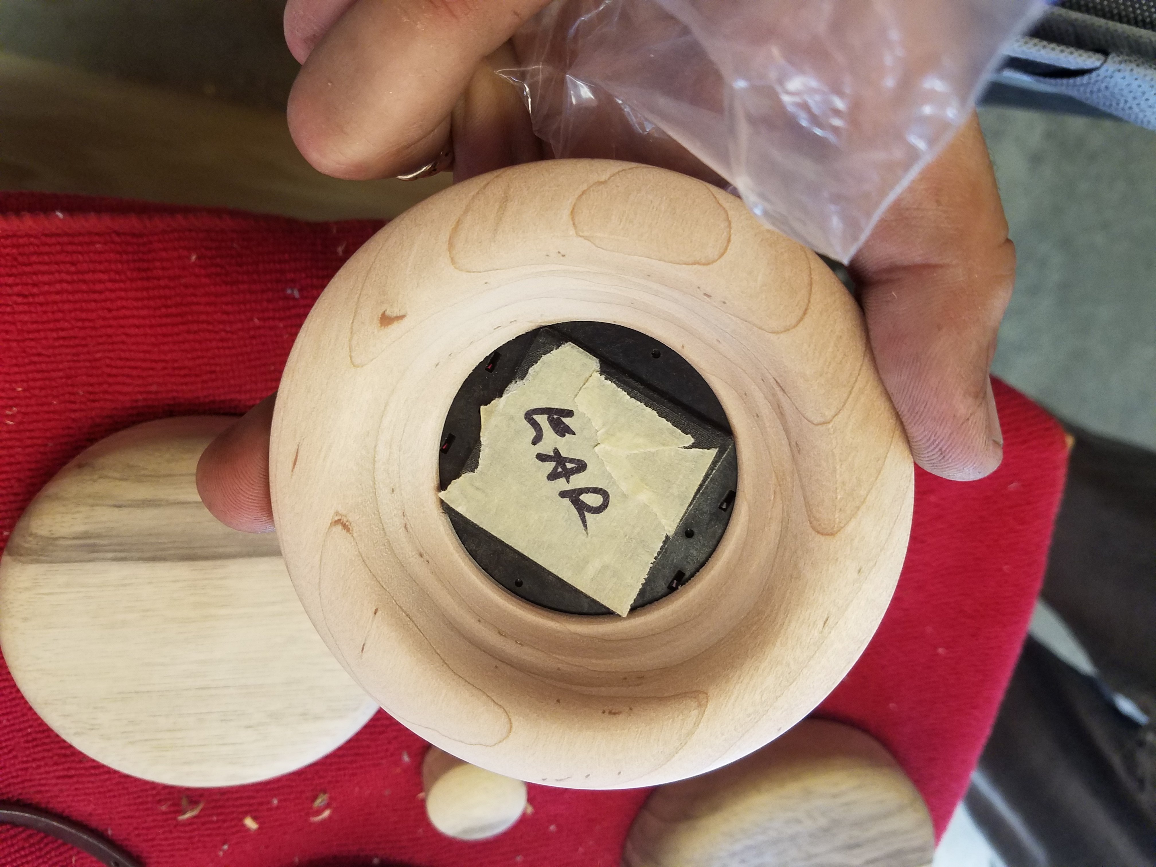
Ah! Well, as long as the driver frame is in the exact same position as on the original baffle there should be no issues there. This should be the case with my part but I will double check tomorrow.
 
Had a bit of listening time with it today and I was enjoying it but I am definitely getting a high frequency peak there (which seems to be characteristic of the stock T50RP too) that I would love to get rid of.
 
I am trying to see how much I can change the sound of the T50RP using fully consistent and reversible 3D printed parts.

 
Aside from trying various materials, internally and ear side, I wonder if the cup and baffle design can be changed to reduce the 10 kHz peak? For example, what effects may result from altering the cup shape, cup depth (and increasing the height of the shock absorber posts to compensate for greater cup depth), changing the cup floor topography, adding cup floor and baffle diffusers, etc.?
 
Sep 1, 2013 at 5:04 AM Post #10,369 of 11,346
what was in the ones you heard?
 
Sep 2, 2013 at 8:48 AM Post #10,372 of 11,346
 
Quote:
this is why people modify it, you can mess around to get highs and lows but there really isnt anything you can do to get mids, so with strong mids the potential is almost endless.

We did modify them and we followed someone's guide from this site. Could barely tell a difference. Neither me nor my friend cared for them much but he doesn't regret the purchase. He did like the ATH-M50s that I traded to him much better though.
 
"what was in the ones you heard?"
 
Blue tack and cotton batten.
 
I do have a clue and that is why I said it is hype. It's like people claiming HD598 sound a lot better than HD595 when they don't. I've had both of those headphones and they sound pretty much identical. More hype!
 
Sep 2, 2013 at 9:01 AM Post #10,373 of 11,346
Quote:
 
We did modify them and we followed someone's guide from this site. Could barely tell a difference. Neither me nor my friend cared for them much but he doesn't regret the purchase. He did like the ATH-M50s that I traded to him much better though.
 
"what was in the ones you heard?"
 
Blue tack and cotton batten.

than you have to be doing something wrong...the sound is literally different with each addition of material inside. There is an incremental thread with graphs for almost every material used. Pads and everything. But I guess to each his own...the biggest change would be changing the pads which i'd recommend. If you really want to hear the difference everyone does follow the bluemonkeyflyer DBV #3 guide
 
Sep 3, 2013 at 4:39 AM Post #10,374 of 11,346
Quote:
 
Aside from trying various materials, internally and ear side, I wonder if the cup and baffle design can be changed to reduce the 10 kHz peak? For example, what effects may result from altering the cup shape, cup depth (and increasing the height of the shock absorber posts to compensate for greater cup depth), changing the cup floor topography, adding cup floor and baffle diffusers, etc.?

I suspect the 10-11 kHz peak is due to driver's dimensions, not the cup..
 
Sep 3, 2013 at 5:10 AM Post #10,375 of 11,346
Quote:
I suspect the 10-11 kHz peak is due to driver's dimensions, not the cup..

 
I rather suspect that too. I can't imagine a square driver is the best in terms of producing a natural wavefront.
 
Sep 3, 2013 at 6:04 AM Post #10,377 of 11,346
leave a small "pigtail" or length of the original wiring still attached to the drivers to solder onto, instead of trying to solder to the driver board itself, unless you are really good at soldering. Even then you can warp that area.  Just an easy option and leaves you room for a few screwups just in case..
 
Sep 3, 2013 at 6:24 AM Post #10,378 of 11,346
Quote:
leave a small "pigtail" or length of the original wiring still attached to the drivers to solder onto, instead of trying to solder to the driver board itself, unless you are really good at soldering. Even then you can warp that area.  Just an easy option and leaves you room for a few screwups just in case..

Well the driver part is easy actually all you have to do is add some solder on your point than set it gently upon the old solder and just wait for it to melt than quickly add your wire inside and lift off the solder point and blow on it so it will quickly cool. Won't even need to touch the fragile part xD i'm thinking more of the cable entry into the cups.
 
Sep 3, 2013 at 7:44 AM Post #10,379 of 11,346
Quote:
guys any ideas on how to cleanly solder wires onto the drivers without leaving too much of a mess? I don't want to use the jacks because they tend to get loose easily.

Get some SPC 19-strand 28 or 30 AWG wire from ebay seller:  navships  This wire takes solder like a sponge, unlike the factory wire of the stock drivers.
Strip off insulation to expose a little more wire than needed and pre-tin.
Lay wire across solder pad.
Use tiny strips of tape to hold wire in contact with the solder pad, on both sides of the solder pad.
Add a little bit of flux with a toothpick to the wire/solder pad.
500 to 550 degrees F.
Pre-tin solder iron tip.
In and out in 1 to 2 seconds.
Snip off the excess wire on the other side of the solder tab.
 
Sep 3, 2013 at 7:53 AM Post #10,380 of 11,346
Quote:
I suspect the 10-11 kHz peak is due to driver's dimensions, not the cup..

 
Quote:
 
I rather suspect that too. I can't imagine a square driver is the best in terms of producing a natural wavefront.

 
That's one possibility. The cup/baffle design is another possibility; or, it could be an interaction effect. Is there any research on this? If not, experimentation is the only way I know to find out. I wonder if any engineers have modeling software that could answer this question?
 
The drivers can't be altered. Changing the dimensions and/or shape of the cups and baffles may result in different FR....maybe better...maybe worse. 
 

Users who are viewing this thread

Back
Top