PinkLed
100+ Head-Fier
- Joined
- May 16, 2013
- Posts
- 199
- Likes
- 13
Sorry - that's my error which has continued through my posts and others'
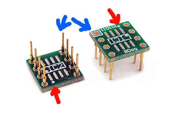
Correct. There is a a small indented dot on the top of the SOIC chip which should be aligned in the same direction as the dot on the adapter (as you have circled). The indent can be hard to see without a good light source. When installing the adapters into the E12DIY, there is a white square around one of the pins (see back left corners of adapters in the picture a few posts up) which should be at the end with the groove in the socket.
Much appreciated, I hope this post helps others looking to use the HA5002. Mouser has them backordered for 10 weeks now unfortunately. They have over 7000 on order!


 (my wallet won't like it much though)