Dsavitsk/Beezar Torpedo Build Thread
Sep 5, 2011 at 7:16 PM Thread Starter Post #1 of 854

tomb

Member of the Trade: Beezar.com
Joined
Mar 1, 2006
Posts
10,890
Likes
1,049
While I'm still working on getting the kits and website ready, I thought I'd post a build thread for the Dsavitsk/Beezar Torpedo amp.
 
To review just a bit, the Torpedo is the latest iteration of Dsavitsk's parafeed designs known as the L'ess Pressivo. There are many links that chronicle the evolution of the basic design on Dsavitsk's excellent DIY website:
http://www.ecp.cc/less-pressivo.html
http://www.ecp.cc/less-pressivo-build.html
http://www.ecp.cc/less-pressivo-plus.html http://www.ecp.cc/less-pressivo-plus-plus.html
 
In my layman's terms, the design is a great representation of a true, high-voltage, transformer-coupled, tube headphone amplifier. One of Dsavitsk's design goals was low cost, too.
 
After a time, I challenged Dsavitsk to bring one of the L'ess Pressivo designs to a fully PCB-based construction. Little did I know that after a quick successful backboard build, the final implementation became perhaps the longest development and prototyping periods for a DIY headphone amp. The reasons are many, but the result is that the design is already quite refined.  The Torpedo is the culmination of that work.
 
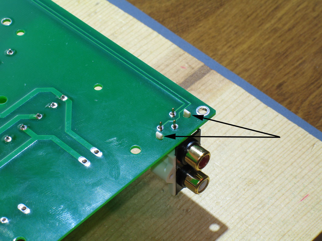
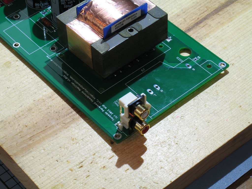
The Torpedo is fully PCB-based with no wiring needed, save a ground wire for the Alps pot and a safety ground wire from the PCB to the case. It uses readily available components, including tubes that run about $2 and less (6J6 - the 6V heater version of the Starving Student tubes). The only exception to that are the custom power and output transformers and a custom-designed case that requires no drilling/cutting. (BTW - most tube dealers say the 6J6 runs into the tens of thousands in stock, so no running out as happened with the 19J6.)
 
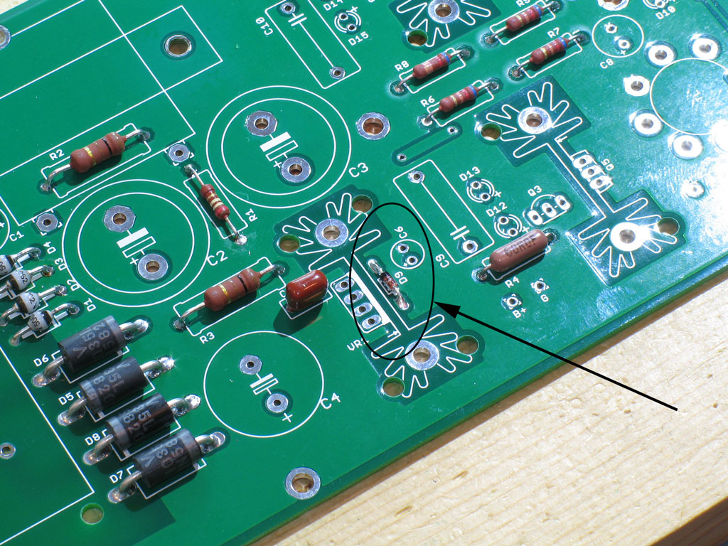
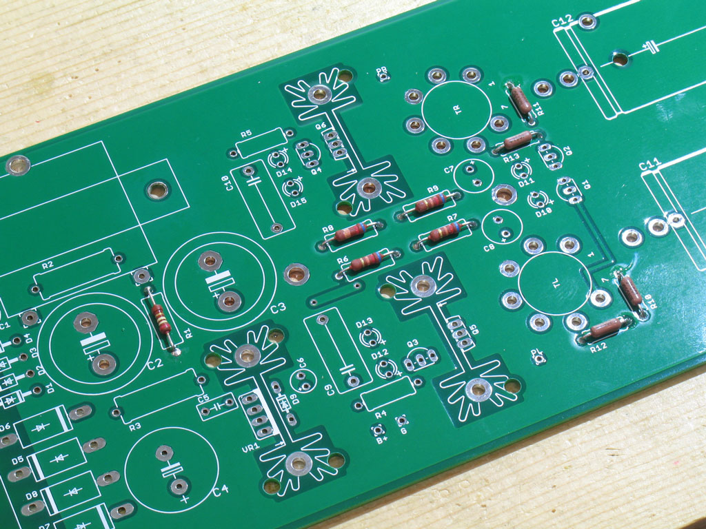
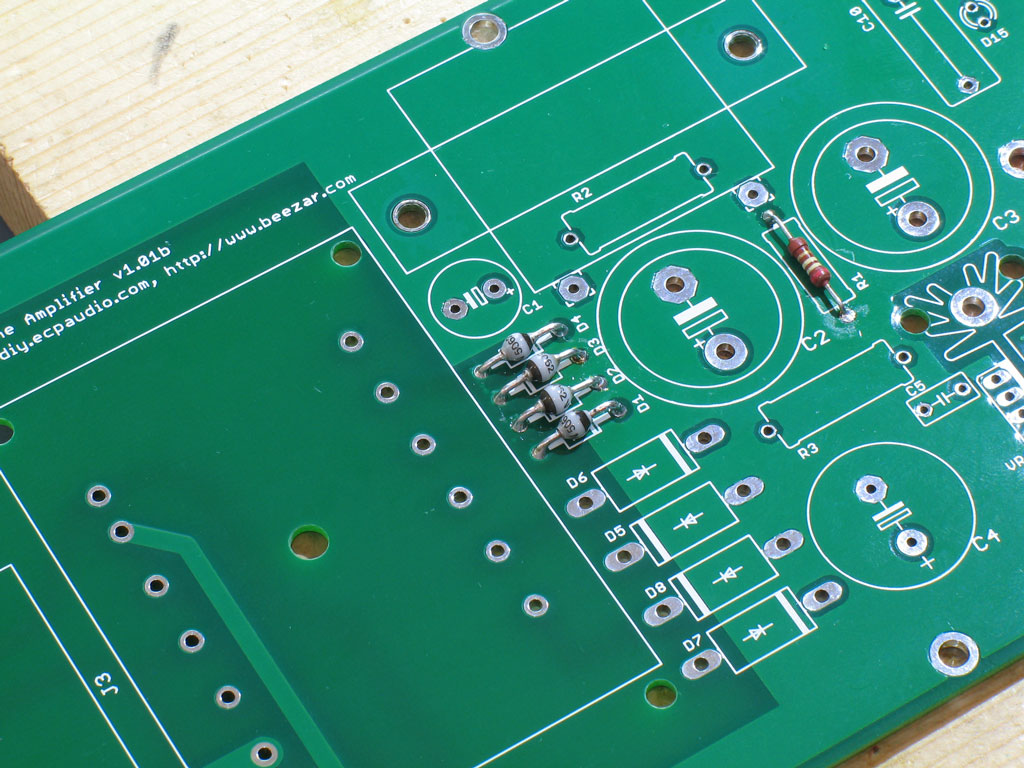
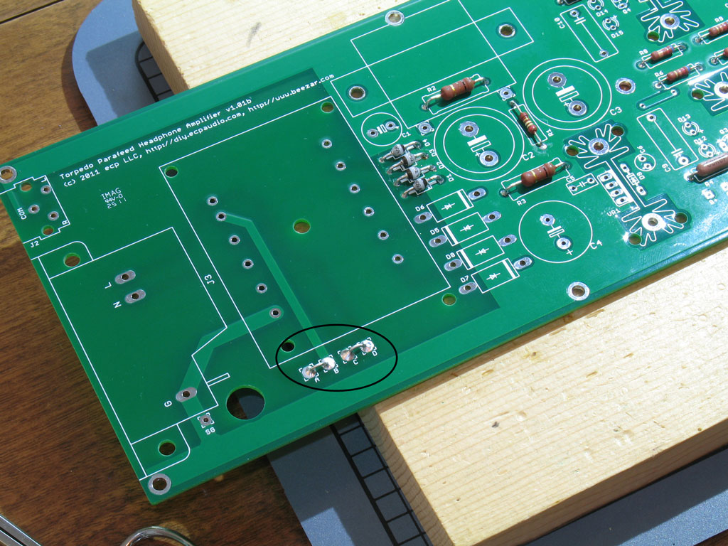
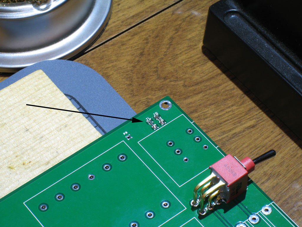
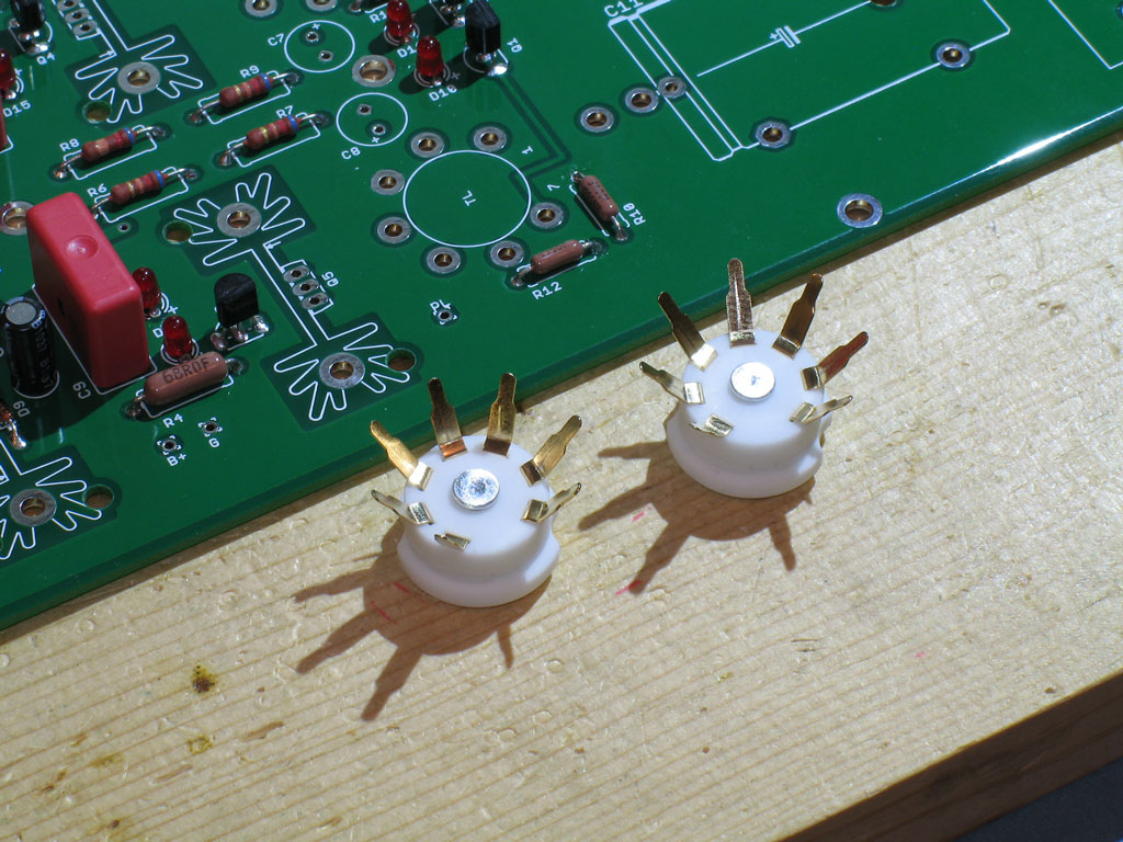
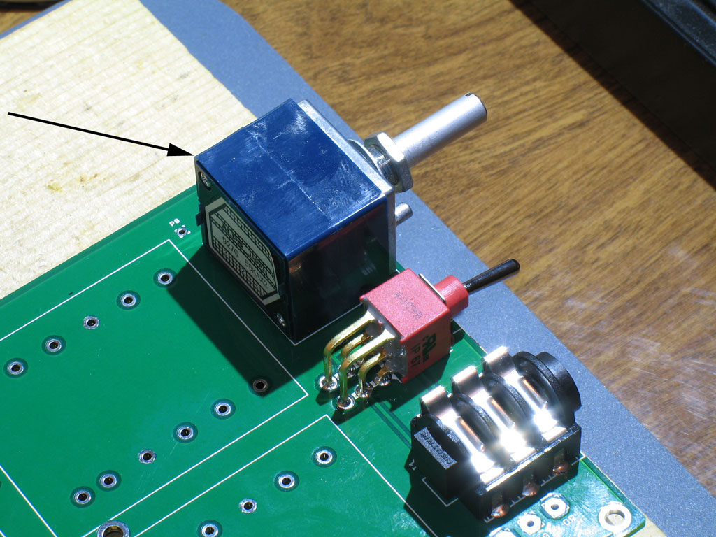
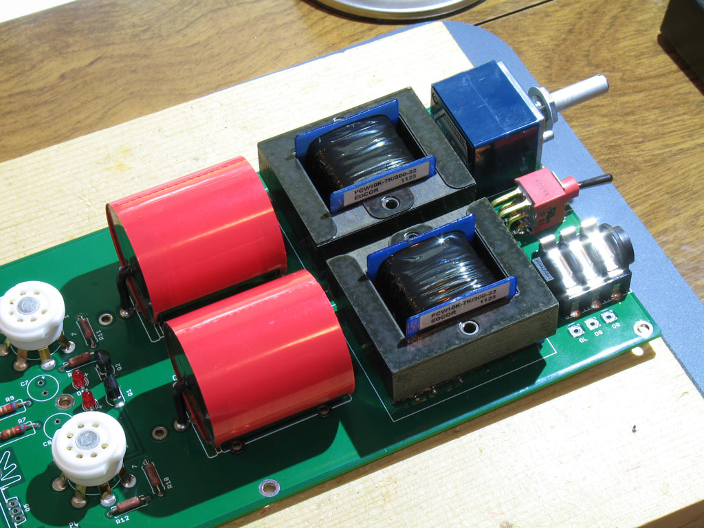
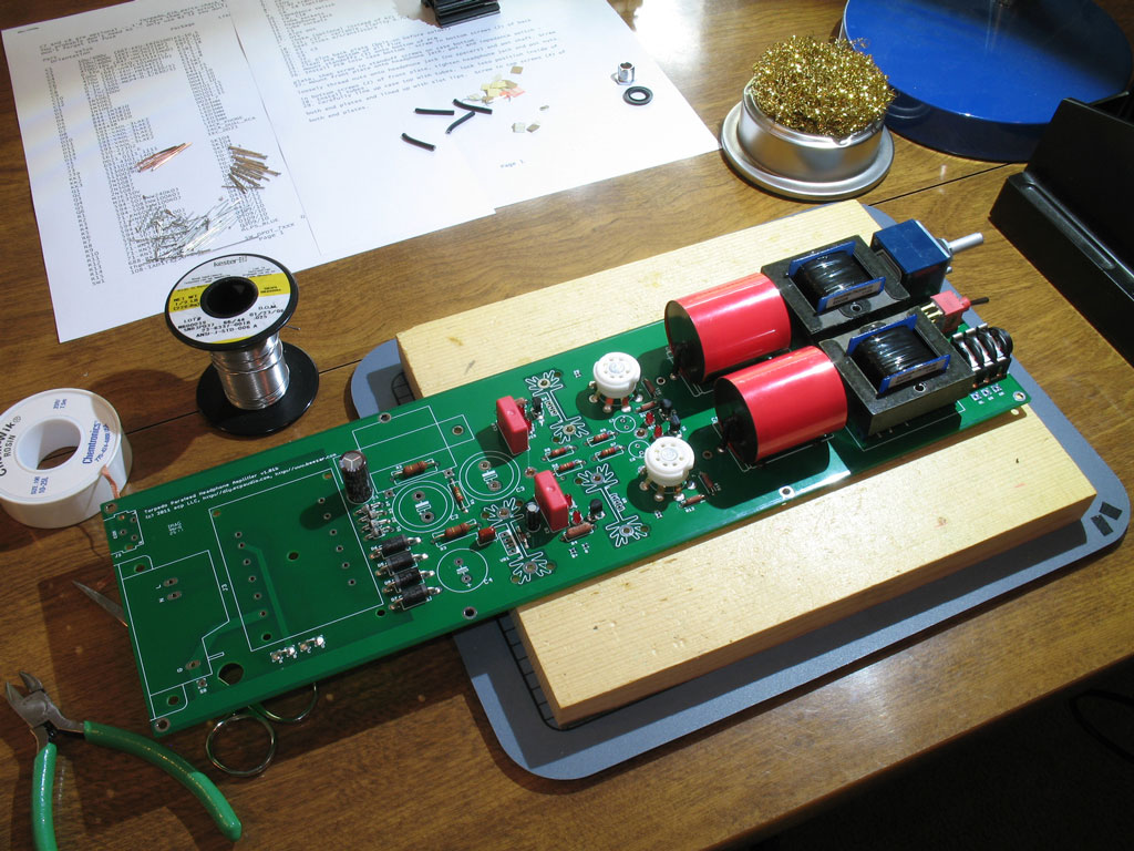
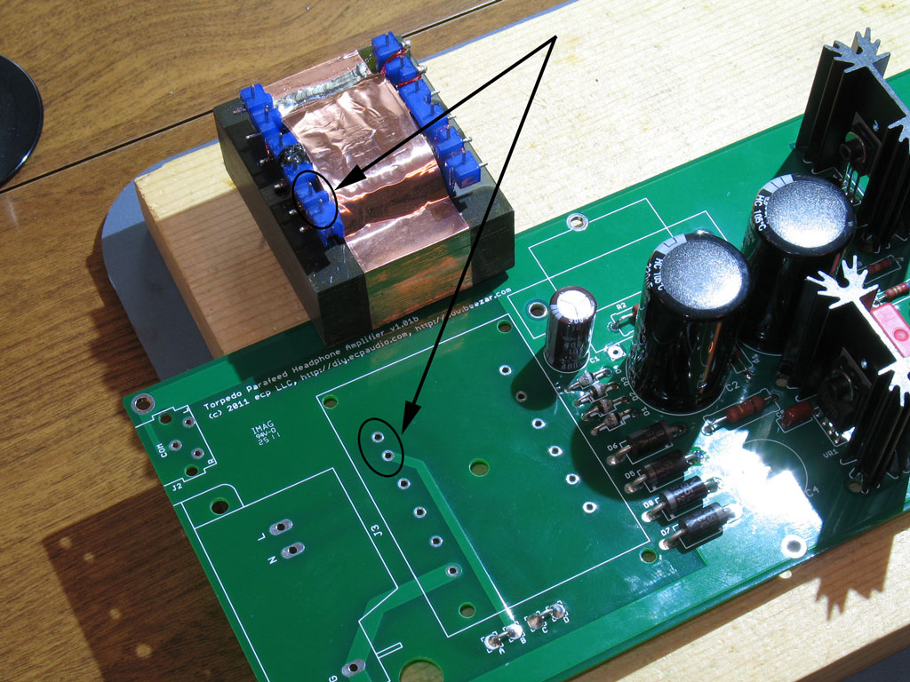
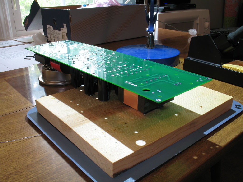
Enough of that, here goes - Pictured below you see the PCB. Yes, it's long. It was done that way to get the power transformer as far away as possible from the output transformers - to reduce any tendency toward hum.

 
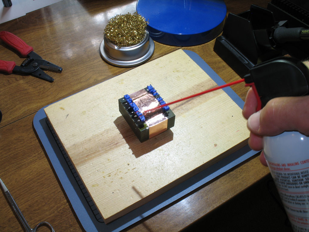
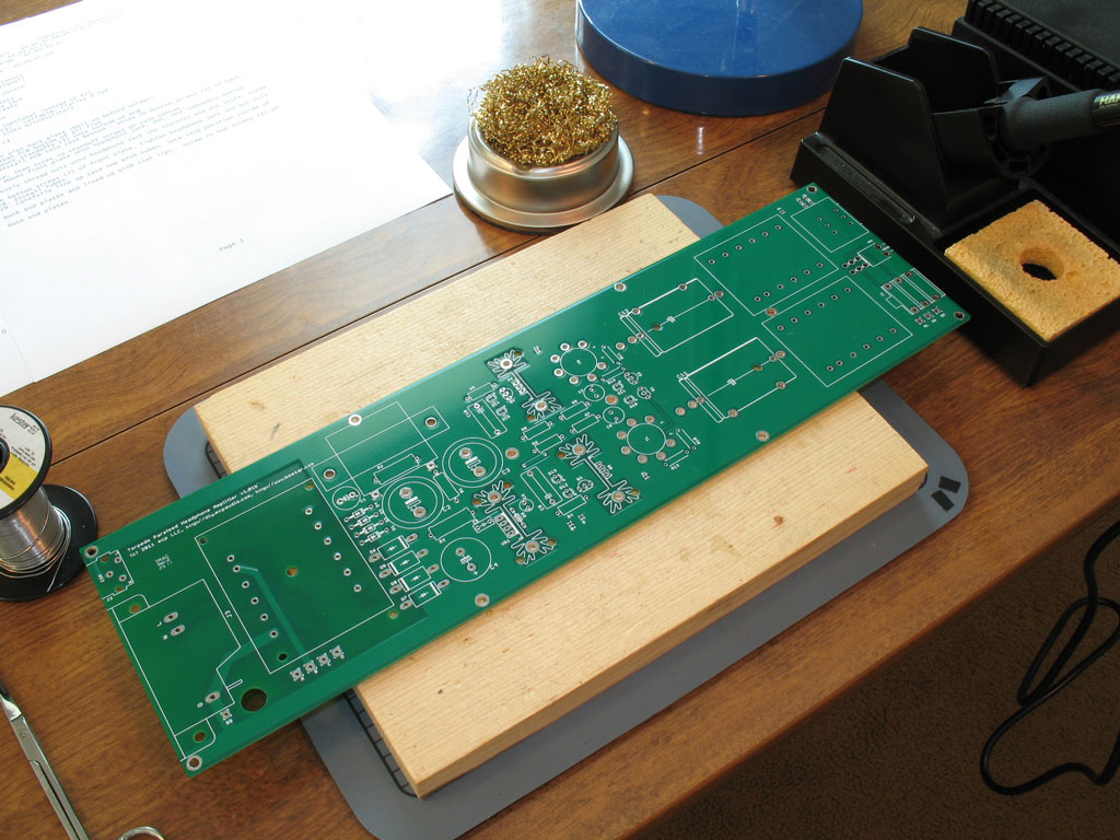
You can also see above, some of the tools that I use to populate a PCB -
  1. A nice, flat piece of high-quality pine used as the building board,
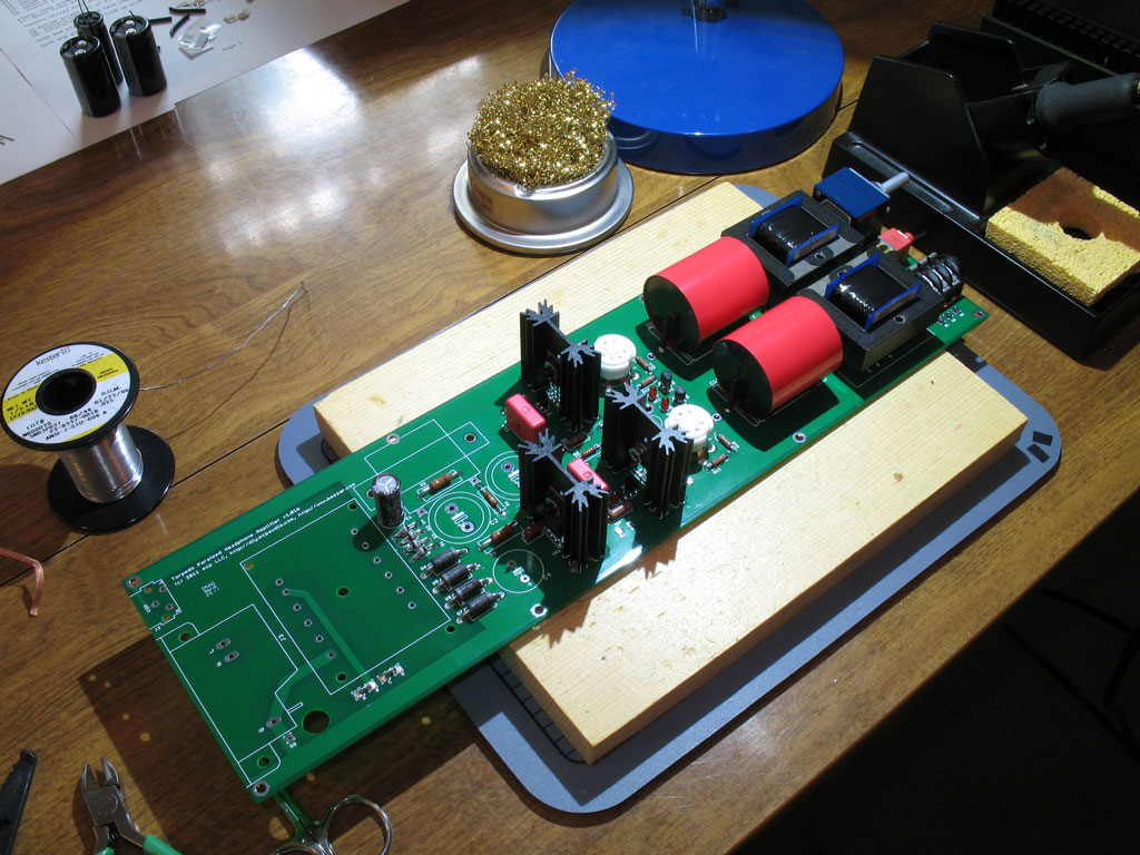
  2. My trusty Hakko 936,
  3. and brass wool to keep the Hakko tip's clean.
 
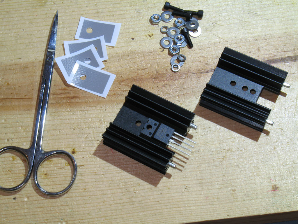
Some of the other tools I use when soldering a PCB:

 
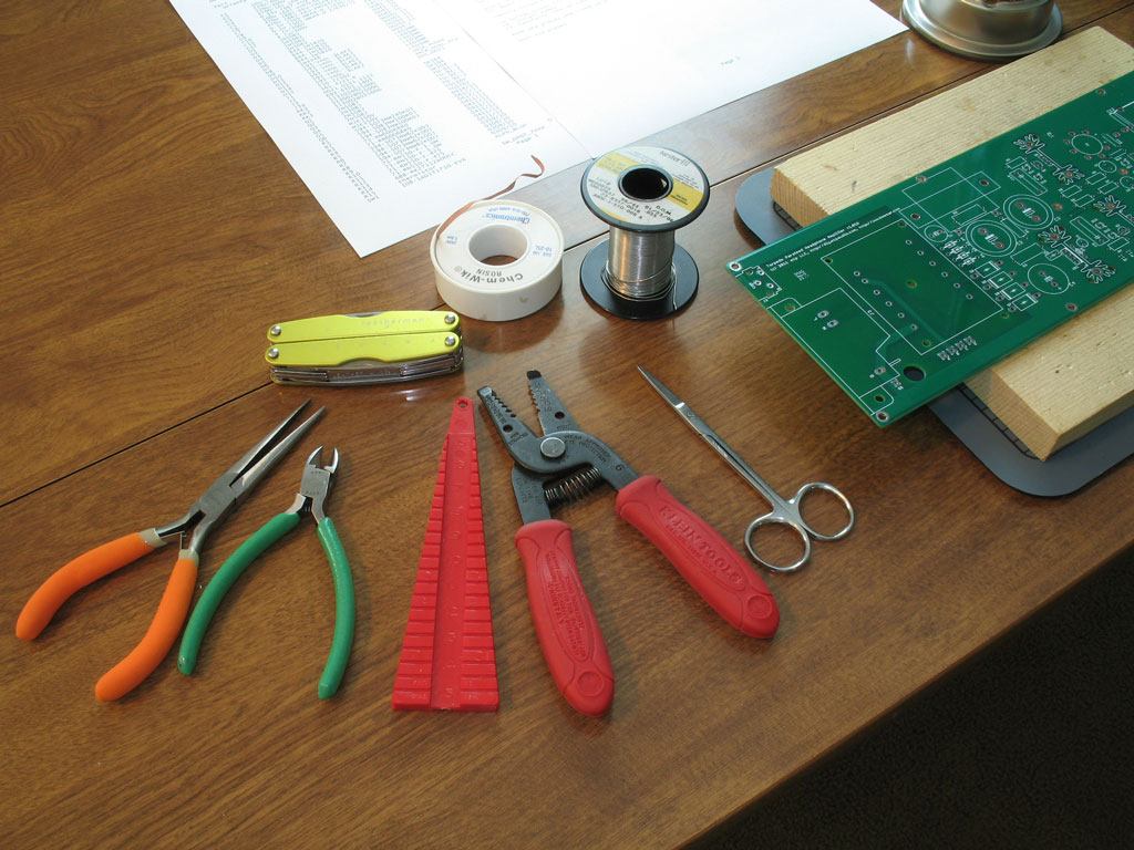
  1. Smooth jaw needle-nose pliers (keeps the marks off of those part leads),
  2. Flush cutters (for keeping the PCB bottom clean and trim),
  3. A lead-bending jig,
  4. Wire cutters/strippers,
  5. Scissors for cutting parts packs, etc.,
  6. A Leatherman for those unforseen quick tool needs,
  7. De-soldering wick, and
  8. Finally, Kester eutectic (63-37) solder.
Your tools may vary, but I find these pretty much cover all my needs for most PCB's.
 
Sep 5, 2011 at 7:34 PM Post #2 of 854
The full building sequence will be posted on the upcoming Torpedo website, but generally speaking, it follows the standard lowest-to-tallest-part construction sequence.
 
Step 1:
Install the lowest profile electronic part, the D9 diode.  (The BOM on the upcoming website will fully detail each part.)  I actually made a mistake and forgot this until later on in my build, but it should be first:

 
Step 2.
Next, install the low-profile resistors.  These include R1,R6,R7,R8,R9,R10,R11,R12, and R13.  The Torpedo PCB was designed to make the greatest use of available parts, so the pads are larger than the standard resistors spec'd in the BOM.  I find it helpful in those cases to use a lead-bending jig as shown here:

 
Next, place all the resistors - with their leads bent - in the proper locations and solder into place.  This is straightforward and no different than any other design.  However ... since the Torpedo PCB uses heavyweight 2oz. copper for the ground plane and the fact that it is 14" long in one direction, you may find that the ground pads have a tendency to "sink" the heat from your solder tip pretty quickly.  IOW, you may have some difficulty in soldering the ground pads.  That's OK - the holes are all through-plated.  Nevertheless, due to the high-voltage characteristics of the amp, I recommend that you ensure proper wicking to the top side of the PCB for all joints.  If necessary on the ground plane pads, please turn the PCB over and add additional solder as needed to ensure a good connection to the ground plane:

 
And here we have all of the low-profile resistors soldering in place:


Sep 5, 2011 at 7:48 PM Post #3 of 854
Step 3. -
Install the High-Voltage rectifiers, D1, D2, D3, and D4.  These are pretty neat little devils.  They're encapsulated in glass.  Again, the voltage they will be handling could be close to 300 volts, so please ensure that your solder connections are hot, clean and fully wicked to the top side of the PCB.  As with the above, please turn the PCB over and add solder (and heat) as necessary to complete the ground plane connections on the top side - if needed:

 
Step 4. -
Install the higher-profile resistors - R2, R3, R4, and R5.  These are shown in the pic below:
 
UPDATE!!Please install the Hammond #154H choke instead of using R2!
 

BTW, you will notice some jumpers at the top of the pic.  We'll install these in Step 5.  One might wonder, seeing as how the jumpers are just about as low a profile part as you can get on a through-hole PCB, why did we wait until Step 5?  Simple - installing the resistors first gives us all of those spent leads that we can pick from to make the jumpers.  At the same time, the board is long enough and the resistor parts are low enough that it doesn't create much of a problem installing the jumpers after the resistors.
 
A note about R2: There is an option to use a choke at this position, instead.  After the extensive prototyping we did, I think the general consensus is that the choke may have caused the introduction of some hum, so we went with the resistor option.  You are welcome to try the choke - the opinions were far from conclusive and the resistor is an easy enough swap-out.  On paper, the choke should be superior and it's possible that the hum/ripple came from the tubes.  We've found that the 6J6 can operate seemingly fine, but can produce ripple if the tube is not completely up to snuff.  So, your choice, but we'll stick with the resistor for this build.
 
Step 5. -
Install the jumpers for the power transformer.  The power transformer is made to use either 120V or 240V input.  For 120V, simply jumper "A" to "B" and "C" to "D."  This is shown in the pic:

Again, good solder joints are called for and be sure you get wicking to the top side.  Remember that this amp uses high-voltage.  Build correctly and cleanly, you will never have an issue.  BTW, international folks who will use 240V input will solder "B" to "C."
 
Sep 5, 2011 at 7:59 PM Post #4 of 854
Step 6. -
Install the Low-Voltage rectifiers - D5, D6, D7, and D8.  These form the basis of the heater supply and while the eventual voltage is only ~6VDC, the current for two 6J6 tubes is quite high.  Hence, the use of the large, Schottky barrel rectifiers.  Those of you who've built a MiniMAX or MOSFET-MAX are probably familiar with these.  Straightforward in installations, bend the leads and solder them in place:

 
Step 7. -
Install the C5 capacitor.  No polarity is needed on this one:


Step 8. -
Install the LEDs - D10, D11, D12, D13, D14, and D15.  No, these aren't tube lights.  Dsavitsk uses a fairly unique solution with LEDs forming the basis of both the CCS (Constant Current Source) and Tube Bias.  Both of these will be explained in detail on the Torpedo website, but suffice to say that not any 'ol LED will work.  The proper LEDs are still plentiful and cheap, but any substitution must be carefully researched for the proper voltage/current relationship.  We recommend you stay with the specified LEDs unless otherwise noted.  Install with the long lead in the pads marked "+":

 
Sep 5, 2011 at 8:14 PM Post #5 of 854
Step 9. -
Install the TO-92 transistors, Q1, Q2, Q3, and Q4.  Two of these transistors are used in the CCS's, while the other two form part of the unique transistor-based tube bias (full explanation on the Torpedo website).  These transistors are familiar to Millett/MiniMAX/MOSFET-MAX builders and are the ubiquitous 2N5087's.  I matched mine, but only because I had them that way from MAX kits.
wink.gif


At this point, you can install the optional capacitors C7 and C8.  I didn't install them and haven't missed them in a previous prototype build.  So, my next step is installing the C6 capacitor:
 
Step 10. -
Install the C6 capacitor.  This is the small electrolytic capacitor that forms part of the circuit for the regulated heater supply:

Oops!  You can see a mistake I made: installing the C9 and C10 capacitors (those red Wima's).  Not a big problem, but the next step should be installing the impedance switch.
 
Step 11. -
Install the impedance switch.  This is a mechanical/electrical connection, so ensure that the solder joints are properly wicked to the top side of the PCB and that the pads are fully-filled with solder:

Note the wicking up along the leads.  Also, do not forget to solder the tabs of the front plate of the switch.  As with all three components at the front of the PCB (volume pot, headphone jack, impedance switch), take care to line everything up and ensure that the part is flush against the PCB.  The reason I use a pine board as my PCB building board is so that I turn the PCB over and apply pressure to the bottom of the PCB while soldering the leads.  This ensures that the parts are flush.
 
Oops!  Dsavitsk snuck this one in on me - there are jumpers in the signal traces to the pot if you wish to wire in a different pot or attenuator.  We're sticking with the venerable Alps Blue Velvet (RK27), so we'll solder in jumpers for these:

 
Step 12. -
We'll ignore my mistake in jumping the gun on the Wima's and you should properly solder them in as Step 12:

 
We'll start out with the tube sockets in Step 13. tomorrow!
 
Sep 6, 2011 at 7:39 PM Post #6 of 854
Step 13. -
Tube sockets!  No drilling for tube lighting here, though - too many high-voltage traces running under the sockets.  That's OK, though, because the amp's PCB already has six LEDs that we installed in Step 8.
 
We recommend the oft-used ceramic PCB tube sockets for the Torpedo as shown below - one wrapped as they come from the manufacturer and one unwrapped:

Inspect your tube sockets carefully.  I've seen some where the tube-pin holes were partially or completely covered by the molded ceramic.
 
Next, I install my tube sockets a little differently than many.  The sockets, their structural integrity, alignment and proper electrical connection are all important.  You may end up plugging and un-plugging different tubes tens or perhaps hundreds of times.  The sockets need to mounted properly to withstand that kind of fatigue.  The electrical connection must be sound to minimize the effects of grounding issues.  Finally, their alignment is also important to prevent permanently crooked tubes for the life of the amp.  De-soldering one of these buggers is difficult, so proper preparation is key.
 
So, I start by splaying out the sockets' PCB pins so that the circle they form is slightly over-sized compared to the PCB pads.  Looking at the pic below, you can see that the PCB pins are bent outward so that they're just outside the PCB pads:

IMHO, this forces you to slightly wedge the pins back inward, so that the fit is tight and secure - everything is pretty much locked into place before you apply the first solder.
 
Here we can see both sockets with their PCB pins splayed out, just prior to placing into the PCB and soldering into place:

 
Finally, solder them into the PCB.  As with previous mechanical-electrical solder connections, ensure that the pads are completely filled and that you get wicking some distance up the pins on the top side of the PCB:

Note that the solder has wicked up at least 1/8" or so on each PCB pin leg.  Turn the PCB over and apply solder to the top, if necessary, to ensure a good mechanical connection.  While soldering on the backside of the PCB, treat the sockets as if you're tightening bolts on a spare tire - alternate soldering opposite pins until you've completed the circle.
 
Sep 6, 2011 at 7:48 PM Post #7 of 854
Step 14. -
Install the headphone jack.  This is pretty standard, as most of you should've installed a headphone jack before.  However, please note earlier instructions to keep the parts flush against the top surface of the PCB and aligned.  The Torpedo front plate has little play and there is no flexibility in adjusting the position of soldered-in parts.

This is another mechanical-electrical connection, so again - try to make certain that the solder joints wick up the top side of the PCB and the headphone jack pins.  If you have trouble with the ground pins (the ones in front indicated by the arrow), then solder some on the top side - but be careful!  The body of the headphone jack is plastic and it will melt!
 
Step 15. -
Install the C1 capacitor as shown:

 
Step 16. -
Install the Alps Blue Velvet pot (RK27).  Be careful here ... the pot should be aligned so that the pot shaft is perpendicular to the front edge of the PCB.  There is some play in the PCB pads.  Solder one joint on the back side and then turn the PCB over.  Check for pot shaft alignment.  You don't want to have a crooked volume knob for the life of the amp.  Use a draftsman's triangle, multiple eyeball views, whatever - just try to get it straight:

 
Sep 6, 2011 at 8:11 PM Post #8 of 854
Step 17. -
Next are the Output Transformers (OTs).  These are custom-designed/specified by Dsavitsk and fabricated by Edcor:

Note a couple of things here ... the pins on the left in the photo above are closer together than the pins on the other side of the transformer.  This is what keys the transformers in place on the PCB.  You can't get them in backwards unless you seriously force something into damage.  Also take note of the plastic pins.  When you go to solder the transformers in place, you will not be able to get them flush to the PCB - only the pins.  So when you look sideways at the transformer and PCB, there will be a gap between the blue plastic skids and the PCB.  This is normal.
 
Prior to placing the transformers on the PCB and soldering them in place, give them a shot of compressed air or similar.  The transformers are packed in closed-cellular foam and bits of the foam may get in-between the pins and/or the blue skids and the metal laminations.  The bits of foam will stink to high heaven when you solder the pins (maybe a bad gas of some sort), so you'll thank yourself for getting them clean of the foam bits prior to installation:

 
Place the transformers in their positions on the PCB.  Locate the two close pins highlighted in the first pic above, and place those in the two close pads on the PCB.  I do this by placing them on the PCB, picking up and turning over the pine building board, placing it on top of the OT's, and then turning over the whole assembly so that it looks like the pic below.
 
 
Both Left and Right channel OTs are the same.  The only thing that differentiates the Left from the Right are the traces on the PCB.  The pads are marked below.  As noted previously, the transformer skids are blue plastic and they will melt.  So, solder completely, but quickly.  Alternate sides to keep one blue skid cooling while you're soldering the other one.  Apply some decent pressure to the PCB so that at least the transformers are flush with the blue locating pins shown in the first pic above.

 
Once soldered in place, they'll look like this:

Note that the PCB assembly will be quite lopsided in weight after this.  Please handle the assembly carefully from here until its finished.  You don't want to bend the PCB too much or put a lot of torque on the traces underneath.
 
Next up are the parafeed capacitors.  I don't actually have this labeled as a separate step, because their position in the build sequence will vary considerably, depending on which capacitors you purchase.  I used the Clarity SA caps (obtained from Madisound), which are some of the largest you can install in the Torpedo.  So, their installation came after just about everything but the very largest parts.

Note that the Clarity caps come with some pretty long leads.  Trim/strip the insulation as shown so that the leads are exposed at the point where the cap will be flush against the top surface of the PCB.  Place them in the most convenient pads (there are several to pick from, depending on the size of the caps) and solder in place.
 
Here they are installed:

 
Just to give an intermediate perspective, here's a pic of a very lopsided assembly at the moment:

As noted previously, keep the PCB properly supported at this point and use caution in moving it around. Saying that it's nose-heavy at this point is a big understatement!
 
Sep 6, 2011 at 8:31 PM Post #9 of 854
Step 18. -
Next up are the large transistors and their heat sink assemblies.  There are three - one each for the Left and Right CCS circuit and one for the heater supply voltage regulator.  Here we see some heat sink kits and a couple of the 1-1/2" tall heat sinks that are recommended:

Note the VR1 heater supply voltage regulator.  Each heat sink comes with three holes, so there's a decision that has to be made about which hole to use to mount the transistor/IC.  The top hole leaves too little leads to solder into the PCB, while the lowest hole has the widest part of the leads below the top surface of the PCB (into the pads, IOW).  So, the middle hole was chosen.  The CCS transistors are not so straightforward in this decision.  It's possible to locate them on the lowest hole, but that will cover some of the slot cutout in the heat sink (used for additional cooling by providing venting).  So, the middle hole is chosen for those transistors as well, keeping everything consistent.
 
Here are the three assemblies made up and ready to install on the PCB:

See the details on heat sink mounting on the Torpedo website.  Essentially for each mounting, you have the following:
  1. socket head cap screw
  2. washer
  3. transistor/IC
  4. thermal pad
  5. heat sink
  6. washer
  7. lock washer
  8. nut
As noted before, those slots in the bottom of the heat sink are intended for additional cooling by providing a vent around the transistor.  So, trim the thermal pads before sticking on so that they do not partially cover those slots.  Also, like the car tire analogy mentioned above, you want these finger-tight, only.  Wait until you get them soldered into the PCB before you torque down on the screws/nuts.  Torque is probably too strong a word, though, because you want to tighten them so that the lock washer is obviously compressed, but not enough so that the thermal pads get cut.  There is high-voltage going through the CCS transistors, so you don't want them shorting to the heat sink.
 
Here we have them placed on the PCB, the PCB flipped over so that you can apply pressure to the PCB/heat sinks - ensuring a flush fit - and supported on the nose-heavy end.  Notice the curve of the PCB, regardless:

Start with the transistor pins, first.  Alternate from one pin on one transistor to another pin on another transistor, then repeat until all of the pins are soldered.  This allows each transistor some time to cool while you're soldering the other two.  When the pins are soldered, then solder one heat sink pin each.  Flip the PCB over for a gut-check on alignment.  If OK, then flip back over and solder the remaining pin on each heat sink.
 
Here we see the heat sinks and their transistors completely installed:

 
Sep 7, 2011 at 2:35 PM Post #10 of 854

 
TomB, is this little area here designated for a choke? The Torpedos I've seen so far haven't used anything here other than the resistor. 
 

Quote:
 
Yep - this was mentioned in Post #3, starting with the paragraph, "A note about R2: ..."
wink.gif

Whoops, sorry about that Tom. I was too busy looking at the pretty pictures :wink: ​

 
Sep 7, 2011 at 4:09 PM Post #11 of 854
Yes, you can use either a resistor or a choke (not both). While a choke does a better job of smoothing the PS than a resistor, it is not clear that this is necessary as the CCS plate loads offer very good ripple rejection. The choke also seems to induce noise elsewhere and in the end may do more harm than good. However, it does eliminate HF noise generated by the diodes that might be more likely to sneak past the CCS. It is really up to the builder to decide whether or not to use it.
 
Sep 7, 2011 at 7:11 PM Post #12 of 854


Quote:

 
TomB, is this little area here designated for a choke? The Torpedos I've seen so far haven't used anything here other than the resistor. 

Yep - this was mentioned in Post #3, starting with the paragraph, "A note about R2: ..."
wink.gif


Sep 7, 2011 at 7:23 PM Post #13 of 854
Step 19. -
Next, we install the big caps - C2, C3, both of which are measly little 220uf, but the important factor is that they're 400V!  Hence, their size.
wink.gif
  I don't know about most of you guys/gals, but this was my first experience at large electrolytic, "snap-in" capacitors.  My whole DIY career, I've looked for which lead was the longest on an electrolytic capacitor, and placed it in the pad marked "+".  Unfortunately, the snap-in leads are short, thick, with a bend for "snapping" into the PCB, and most important of all - of equal length.  So, now we use that white stripe on the side of the capacitor that indicates the negative side, instead.  Here they are installed - you can check yourself where the stripes are oriented to confirm your own:

C2 and C3 are the two caps pointed to with the arrows at top.  Same-same with installation, turn over the PCB, make sure the end with the OT's is properly supported (or at least supported in some way), apply pressure while soldering to keep the caps flush with the PCB.
 
Step 20. -
Next up is the last cap - C4.  This one is in in the heater supply, so low voltage, but lots of uf's - 4700uf and 16V.  It's Step #20 because it's actually a bit taller than C2 and C3.  Follow the same procedure described above to install:

Same photo, but C4 is the cap with the arrow at the bottom.
 
Sep 7, 2011 at 7:39 PM Post #14 of 854
Step 21. -
Now comes the Power Transformer (PT), the big Kahuna!  Pretty soon the PCB is going to feel and act like a giant barbell with lots of weight on the ends - ready to bend in the middle at a moment's notice.  So, remember to minimize the torque on the PCB as you install the PT.  Shown below is the PT next to the PCB:

In a similar manner as the OT's, the PT is keyed with two pins on one end that are closer than the rest.  Take note of those pins as shown in the pic, and place the transformer into the PCB pads accordingly.  Also note that unlike the OT's, there are no plastic post spacers that will prevent the blue plastic rails from being flush to the PCB.  That said, the there's a lot of windings and pins there and it may be too much to ask Edcor to keep those blue plastic rails perfectly flush.  So, yes - you can get a large portion of the rails flush with the PCB, but probably not for their entire length.  That's OK - just do the best you can.
 
As with the OT's, the PT is packed in close-cellular foam when it was shipped from the factory, so there may little bits of foam caught in spaces between the plastic rails and elsewhere.  This pic shows me using some canned air to blow out all of those foam bits:


Here we see the PCB flipped over and ready for soldering the PT in place.  As with the OT's, I placed the PT on the PCB with the PT's pins in the proper pads, place the pine building board on top of the PT, and then flipped the entire arrangement so that it was upside down as shown in the pic:

Be sure to support the OT's and the front of the PCB as shown.  It would be a shame to try to solder with the huge curve that weight on the end will inflict on the PCB.  That would probably end up popping some traces.  So, use some caution and make sure the PCB is supported on the ends.
 
As with the OT's, the blue plastic rails will melt pretty easily if you leave the heat on too long.  So, solder hotly and quickly, but not so fast that you might get cold joints.
wink.gif

 
Finally, we see the PT installed and the PCB is now taking on a much more symmetrical look from front to back:

All that's left are the RCA jacks and the IEC inlet!!
 
Sep 7, 2011 at 7:46 PM Post #15 of 854
Step 22. -
Install J2, the RCA jacks.  Part of Dsavitsk's excellently refined design is the use of some PCB-mounted RCA jacks.  I was suspicious at first, but these have worked out well on the prototypes and I sure am glad to not have to do any wiring!!
 
Here's a shot of the RCA jack assembly - note the claw pins on both sides.  You simply punch these into the outside holes on the J2 area of the PCB and then solder the three pins - Left, Right, and Ground:

 
A shot of the RCA jacks with the claw pins snapped into place on the PCB (support the front of the PCB again!).

 
After applying solder to the three signal pins, here's where we're at:

 
Next - the IEC (tomorrow, I hope!) and we'll be done with the PCB!
 

Users who are viewing this thread

Back
Top