A Very Compact Hybrid Amp
Oct 14, 2014 at 2:18 AM Post #2,206 of 2,218
  Hey guys is there any Hybrid amp for  CIEMs that give me warm lush mids/vocal and fun extended Treble which is fun? also fun bass if possible

i had WA7 with EH Tubes, was't this fun :<  Super mids i know but the Treble and Bass were tube level though that the EH tubes were the best option for that
 
desktop amp if possible else i will go with the current options :/ 
 
 
PS: i am a Treble head and i don't mind a punchy bass that isn't in the way of my forward/sweet/lush/transparent mids :p


If I recall, my HiFiMan EF2 hybrid amp with Raytheon 6AK5 tubes was good with my IEM, but you might want to search for my review to confirm that.  It's not super powerful with todays orthodynamics, but it's good with Grados and HD800 alike.  This is of course using it as just an amp, with an upgraded DAC.
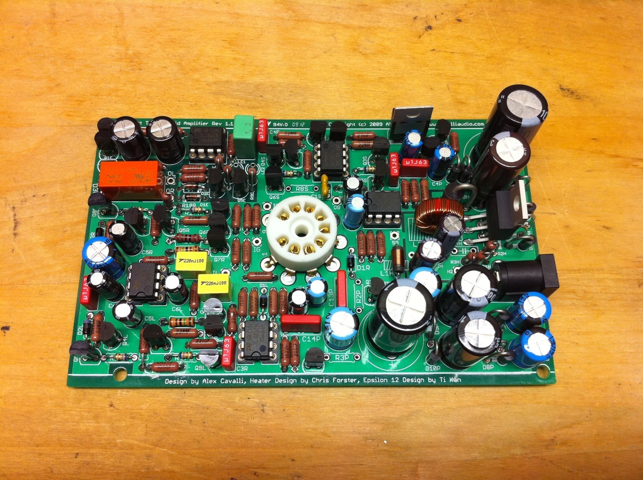
 
Oct 14, 2014 at 2:39 AM Post #2,207 of 2,218
I'd have to say the CTH unfortunately wouldn't be a good choice for CIEMs. There is a slight 60hz buzz with this amp that is for some reason inherent in the design. It's not bad at all with 95% of the headphones I use. You notice it with IEMs because of their high sensitivity.
 
Mar 16, 2015 at 1:59 PM Post #2,208 of 2,218
Need help to troubleshoot a problem while performing an initial start up smoke test.

Plug in the wallwart and wait for at least 2 minutes. If there is smoke turn of the amp immediately, but if not wait.

Had to replace C1P. It was reversed :rolleyes: It bulged but did not short. (Measured 1.3MΩ after removal.)

The indicator should go from red to green.

Remains red.

Whether it does or doesn't, check these voltages anyway.

Measure between OG and SG. This should be very close to 12V..

I'm getting 23.1V here. - What should I be checking next to isolate the problem?

I wonder if IC1 (TL082CN) was damaged when C1P popped?
 
Mar 17, 2015 at 2:29 PM Post #2,209 of 2,218
Could you also please take a look at CTH debugging link in my sig & respond to anything else it might query?:
http://www.head-fi.org/t/398839/a-very-compact-hybrid-amp/2175#post_7837361
 
When something goes wrong on this small of a board, with this many parts, it can be difficult & painful to diagnose.
Wouldn't hurt to re-check (all?) other parts, orientation & soldering.  
C1P is part of the LV supply that feeds the "main" portions of CTH, e.g. the input / output / rail splitter stages - most all the ICs & other "sand" (TO92s).  That stuff is more tricky to diagnose & repair than the heater & HV sections.
 
Mar 17, 2015 at 5:41 PM Post #2,210 of 2,218
I just cleaned the flux so will wait until tomorrow to let it dry and take measurements.

Meanwhile, I'll get this out of the way...
The two pairs of yellow wires are temporary for the heater rotary switch and PS fuse.
The OpAmps have been temporarily removed. Verified orientation of all relevant components multiple times.

Looked over all joints with magnifier several times.
 
Mar 18, 2015 at 8:08 AM Post #2,211 of 2,218
Measure between OG and SG. This should be very close to 12V..

I'm getting 23.1V here. - What should I be checking next to isolate the problem?

I wonder if IC1 (TL082CN) was damaged when C1P popped?

 
Others may know better but I'd focus on rail splitter then output buffer sections - see CA DIY orig CTH site.  Swapping out the chips in those sections with known-good ones could be the easy/happy path but wouldn't be surprised if you'll have to go after TO-92s as well (RS then OB).  TLE2426 would be the first I'd pull & swap. 
 
But as one with little patience for tedious sequential replacement myself, and given the possibility of new parts being damaged by state of other damaged ones, I went shotgun on those sections the time I had a problem there myself.   IOW if ordering parts I'd order all sand in RS & OB sections and be prepared to replace.
 
Mar 18, 2015 at 11:34 AM Post #2,212 of 2,218
Others may know better but I'd focus on rail splitter then output buffer sections - see CA DIY orig CTH site.  Swapping out the chips in those sections with known-good ones could be the easy/happy path but wouldn't be surprised if you'll have to go after TO-92s as well (RS then OB).  TLE2426 would be the first I'd pull & swap. 

But as one with little patience for tedious sequential replacement myself, and given the possibility of new parts being damaged by state of other damaged ones, I went shotgun on those sections the time I had a problem there myself.   IOW if ordering parts I'd order all sand in RS & OB sections and be prepared to replace.


This is interesting...

With all five OpAmps (ICE, ICL, ICR, IC1S {TL081} & IC1 {TL082}) removed I applied power.
After about 10 secs I heard the relay click and the LED went red to green.
Now OG to SG = 12.5V (Yay?)

Output of the ICP voltage regulator = 24.1V

New OpAmps and TO-92's were ordered yesterday.

FYI - The TL082CN in DIP packages are getting scarce. Production has ceased.
The main suppliers (Mouser) only have them in a SO-8 (SMT) package (TL082CDT). An adapter would be in order if pressed.
However, sellers on eBay and Amazon are still stocked.
 
Mar 18, 2015 at 3:15 PM Post #2,213 of 2,218
FYI - The TL082CN in DIP packages are getting scarce. Production has ceased.
The main suppliers (Mouser) only have them in a SO-8 (SMT) package (TL082CDT). An adapter would be in order if pressed.
However, sellers on eBay and Amazon are still stocked.

AFAIK there's nothing special about the TL081s & TL082s as used in CTH circuits & they don't lie in the (direct) audio signal path, e.g. TI & other makers of that spec would be fine.  Think BB OPA134s & OPA2134s are also good if pricier substitutes (IIRC they are what I happened to use in CTH's 1st breadboard proto).    Otherwise sticking with (J)FET input stage opamps, with same/"standard" pin-out, and comparable datasheets should ID others.
 
BTW *if* RS keeps any stores open or maintains website sales (& follows through with such sales:), they appear to have TL082s: http://www.radioshack.com/tl082-tl082cp-wide-dual-jfet-input-op-amp-8-pin-dip/2761715.html#.VQnIuGaJKHk
 
Feb 5, 2018 at 11:19 PM Post #2,214 of 2,218
The cth was on my mess of a work-table for 4 damn years. The story is that I had decided to rewire the amp using nicer wire and to install a TKD stereo pot. The wiring went mostly well, I say mostly because the round metal ring came off where you would connect the input ground. After installing the new volume pot, and wiring the same as the rk27 before it (or so I remember), the damn thing started picking up Spanish radio.. had me scratching my head. Anyway, at that point I also had a EHHA so I left it on my bench. I got back to it a few times in the years since, trying different wiring schemes, no luck.

Had some days off recently, so gave it another go. Wired in the old pot, it worked! Not wanting to be beat by the TKD, I tried to connect it, first using jumpers to test. Seemed to be working, some hum. The TKD is about twice the size of the Alps rk27, so had to take care wiring and mounting it. Did that, reflowed IG.

The little beast is alive! Sounding better than I remember. A few extra holes on the front, and the screws that I didn't lose aren't doing all too great of a job holding the front and back panels on the hammond case, will need to get creative to fix that. But should be doable.

I should also mention previous to all this I had blown some transistors on it while tinkering with it, had gone through and replaced them all. A few caps swapped as well. I'm surprised it's held up.

Feel quite a bit of nostalgia listening to it. This thing is a keeper, will be holding its residency in my office, along with a Headroom Micro DAC. A shout-out to @runeight , you're a goddamn legend!
 
Last edited:
Feb 7, 2018 at 3:17 PM Post #2,215 of 2,218
well, spoke too soon, the wire connecting to IG on board broke off. I don't think I will be able to connect IG to the board anymore, it's stripped, and pretty much done. Looking at the board, it looks like IG (input ground) is isolated from rest of the board. Can I put in a piece of metal on something like a nylon stand-off and use that as IG? Any other ideas of how I can work-around this?

IMG_20180207_130816.jpg
 
Feb 7, 2018 at 9:58 PM Post #2,216 of 2,218
IG is input ground. You can tag IG wire along with any nearby component's connection to ground (PCB top layer). E.g. R1L resistor's lead/pad right next to IG pad, or nearby R1R lead. You can see their pad connections to PCB top-plane/ground and use ohmmeter to confirm. Note also that IG=SG.
 
Last edited:
Feb 7, 2018 at 11:51 PM Post #2,217 of 2,218
IG is input ground. You can tag IG wire along with any nearby component's connection to ground (PCB top layer). E.g. R1L resistor's lead/pad right next to IG pad, or nearby R1R lead. You can see their pad connections to PCB top-plane/ground and use ohmmeter to confirm. Note also that IG=SG.

Wired it to same spot I had SG connected. Worked out well, least messy. Thanks for the tip!!
 

Users who are viewing this thread

Back
Top