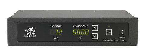
The independent power supply helps a lot because it is no longer dependent on the weak and noisy USB 5V supply, which can only supply up to 500mA of current, that can drop to 100mA in some cases.
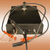
If you are interested in a better power supply consider replacing the power transformer, I have a similar unit based on the previous generation XMOS and it came with the green Bingzi transformer. I wanted something that was UL rated and replaced it with an Amgis/Alfamag, the bonus was it ran much cooler and the Alfamag was about 10% heavier (more copper in the windings)
Outside of the US, Talema is easier to find and a little cheaper.
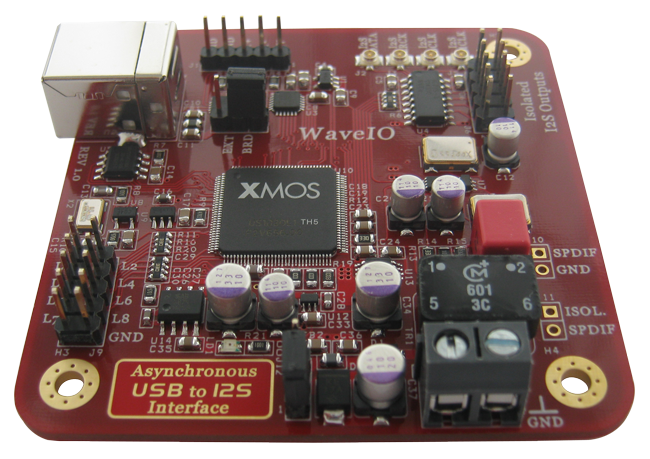
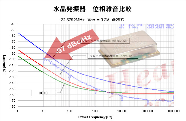
I also installed ultra low jitter crystal XOs replacing the "Precision 0.1ppm" ones that it came with.
The Gustard looks like it has separate regulators for the XOs so it is probably worthwhile to put in a low jitter unit.,
The last part is to replace some of the caps with Panasonic OSCONs and Nichicon FP Polymer caps.
The main rectifier filters I used the Chemicon KZN. The KZN has 2x lower ESR than the supposedly Panasonic PX caps
(I think the PX are fakes)
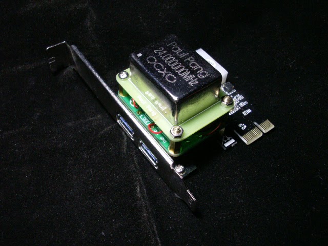
Pictures of my unit.


")


