Cavalli Compact Tube Hybrid (CTH) Tube & Tweak thread.
Jun 17, 2009 at 4:37 AM Post #211 of 691
I've tried Wimas, Obbligato Gold (just as a looong lead/e12 value test, no critical listening)

and I have some russian teflons and pios, and now some Soniccaps to try 'someday...'

Smeegy - thanks for the offer! Doubt Sachu will ever get 'done' with them.
tongue.gif
 
Jun 17, 2009 at 4:47 AM Post #212 of 691
heh,
well I have plenty to keep me busy and I won't miss the k1k for a while so no problems. I guess I could order some Auricaps or similar next payday and see. I'm wondering those terminal blocks fit the cap holes? That way I could screw tight any cap I wanted. If not, where do you find sockets for such things?
 
Jun 17, 2009 at 11:03 AM Post #214 of 691
Quote:

Originally Posted by rds /img/forum/go_quote.gif
Maybe not the best segway into my post...
I've been won over by the Auricaps. <snip>
Like I said, I'm won over, and I'll be ordering a pair of Auricaps for my own CTH tomorrow.


It's great to get this info out there... I think the small point Bill & I are trying to make is that rolling coupling caps, w/o using SIP socket or something (Edit: like these but their holes aren't really big enough), is tough on the PCB. And more difficult in CTH than some amps due to the tight PCB tolerances & quarters.

Its great to ID C4 options, esp those that fit in the BoM case.
 
Jun 17, 2009 at 12:21 PM Post #215 of 691
Quote:

Originally Posted by smeggy /img/forum/go_quote.gif
heh,
well I have plenty to keep me busy and I won't miss the k1k for a while so no problems. I guess I could order some Auricaps or similar next payday and see. I'm wondering those terminal blocks fit the cap holes? That way I could screw tight any cap I wanted. If not, where do you find sockets for such things?


Well, since you are generously offering, I accept (now I can bug Sachu too!)

I'll send you a 'cap rolling' starter kit with Sonicaps, Wimas, and PIOs, and some sip sockets. PM me your address, plz...

I had considered including a strip of SIP sockets in the kits at one point. I may do that in the future (or offer a 'tweaker's kit')
icon10.gif
 
Jun 17, 2009 at 4:54 PM Post #216 of 691
Ooh thanks
smily_headphones1.gif


Actually, looking closer at the board last night it does have those mounting pins already but the caps are soldered in. I had a small issue with the caps being a bit loose so I fixed it with solder
redface.gif


oops.

Anyway, at least the caps are not soldered directly to the board so replacing them will be less dangerous.

Thanks for the offer, PM coming your way.
beerchug.gif
 
Jun 18, 2009 at 1:12 AM Post #218 of 691
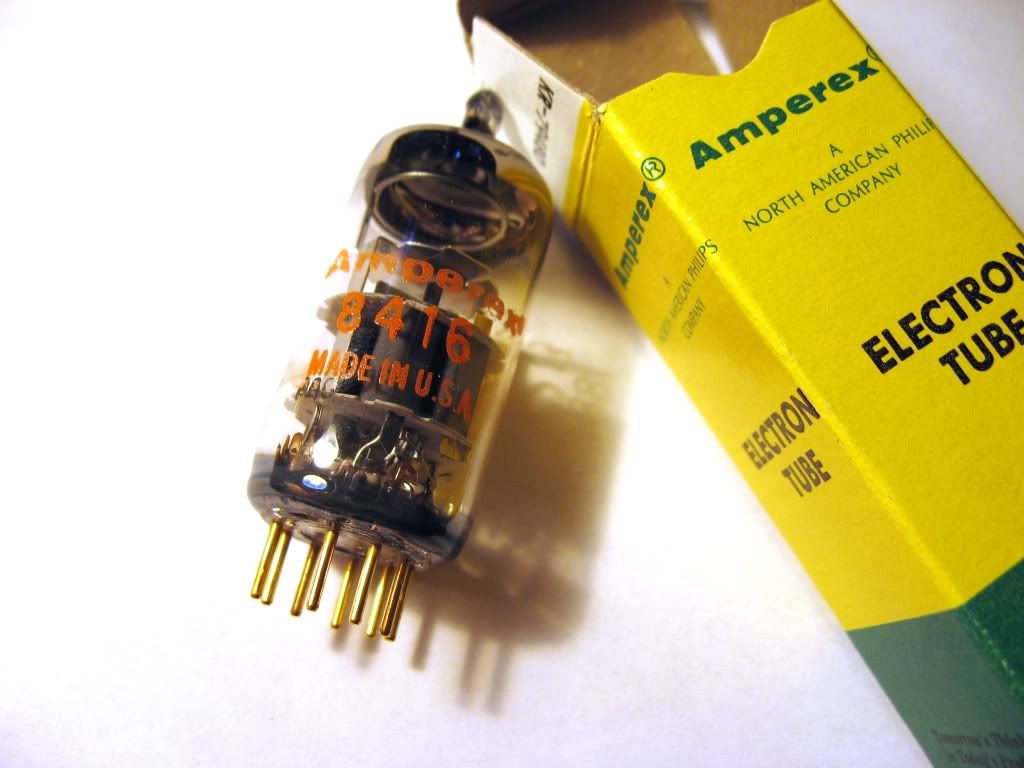
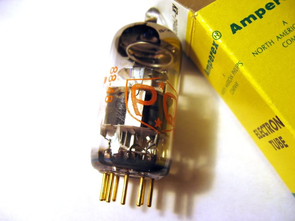
I dont know if my amp would support that tube. It looks like a very interesting tube though.

Only thing is, it was made in America and not Holland, its not a real Amperex. Unless I am misunderstanding the box.
 
Jun 18, 2009 at 1:26 AM Post #219 of 691
Quote:

Originally Posted by rds /img/forum/go_quote.gif
Does anyone have experience with these tubes? They look brand new, and have gold pins
biggrin.gif

EDIT nevermind, could have used the search function
tongue.gif
But now you have some nice pictures


Yep, we just discussed these 8416s few pages ago(?) 12.6v heater 6922s is what I think runeight refered to them as.
Think its a fav of adamus... So I picked one up & have been listening to it a couple days. I like the sound. Like the Amperex 6dj8s I "raved" about a while back but with more detail.
 
Jun 21, 2009 at 8:04 PM Post #223 of 691
So, after seeing a couple tubes were tried in CTH that had other than 6.3v & 12.6v heater and found to work & sound good, knew there was nothing keeping the design from directly supporting more heater voltages.

Nothing but a few more resistors & a way to switch among them.

Calculated (ideal) R3H values for various heater voltages:
Votage / R3H (ideal)
4.2v / 3.3k
5.6v / 5.8k
6.3v / 7.4k
7v / 9.3k
8.4v / 15.1k
9.4v / 23.3k
12.6v / <none>


Wiatrob was willing to test & confirm things & has done so using 4BQ7A, 5BQ7A, 7AU7 and 9AU7 tubes. This tweak further extends tube options in the CTH beyond 6.3v & 12.6v heated tubes. So users of a CTH with this tweak have an even larger selection of tubes to choose from, probably finding some very good deals for tubes running at non-std heater voltages.
Edit: So beyond the 6.3/12.6 tube list, this tweak should add those above, 7DJ8 and 8FQ7 and there are likely more overlooked (e.g. 6AU7, 6BQ7)

The challenge is choosing which heater voltages you want & finding a SP#T switch to switch among them. We found a nice 1/2 inch dia one that can be configured for 2 -> 12 positions:


Wiatrob can chime in w/more info, but I think it remains to be seen if this tweak can be squeezed into the BoM case.
 
Jun 21, 2009 at 8:26 PM Post #224 of 691
Quote:

Originally Posted by cfcubed /img/forum/go_quote.gif
Wiatrob can chime in w/more info, but I think it remains to be seen if this tweak can be squeezed into the BoM case.


Thanks for coming up with the idea and R values!

I'll post some more pictures later this evening. I think it is possible to fit this in the BOM case if you sacrifice the space above the AC jack and keep your resistor leads very short (mine are a wee bit longer than needed). The rotary switch and resistors end up living right in the space above the heater resistor switch leads. I'll test this as soon as time allows.

BTW - this test build supports all the heater voltages mentioned in Chris' post. I left the rotary configured as a 12 position and alternated soldering resistors, so it's not the most compact implementation.

BTW - 7Au7 and 9AU7 RCA Cleartops sound quite good - I know they don't have the biggest following among this group, but at $2.00 a piece...
smile.gif
 
Jun 21, 2009 at 9:58 PM Post #225 of 691
Just to clarify what this is... It's the possibility to extend CTH's heater values from 2 (6.3, 12.6) to more. This would be done by NOT populating the R3H spot on the PCB and instead running wires to those pads & using a single-pole switch with more than two "throws".

In the JPG below, one R3H pad lead would go to the wiper "A" and each of the desired heater resistors would go on #1 -> #whatever switch terminals. All the "loose" ends of those resistors would be soldered together & shrink-tubed to a wire leading to the other R3H pad. There still would be only one R3H value seen by the PCB at a time.


Users who are viewing this thread

Back
Top