Stax SRM-T1 Repair, Re-Cap, Mod

Nov 27, 2022 at 3:33 PM Post #76 of 89
this is a different application with different currents, don't know if it makes any difference.
however i have never seen or heard of a problem with my current source board, or any of my boards
with the ccs circuit on them. (kgst,bh,kggg, t2 with this ccs, grhv) etc.

maybe the 1k resistors you are using are spiral cut film resistors, that certainly could cause trouble.
the dale resistors definitely work fine.
 
Jan 8, 2023 at 3:31 PM Post #77 of 89
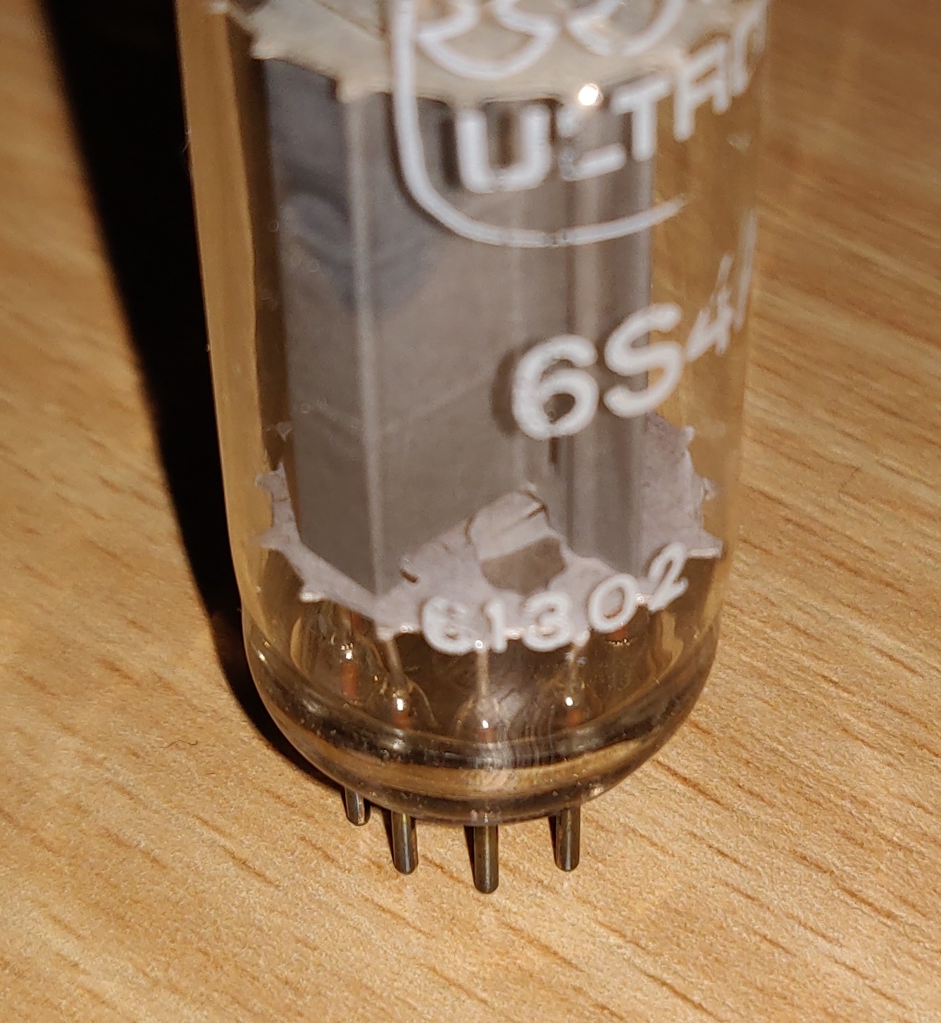
Has anybody ever seen getter (?) material chipping off 6S4A tubes for no apparent reason before?

IMG_20230108_165455.jpg


Any idea what the root cause is? Balance of the affected channel is about 275V now, even after replacing the tube, yikes. Offset can be adjusted to about 0V.
 
Last edited:
Jan 8, 2023 at 3:56 PM Post #78 of 89
Has anybody ever seen getter material chipping off 6S4A tubes for no apparent reason before?


Any idea what the root cause is? Balance of the affected channel is about 275V now, even after replacing the tube, yikes. Offset for L+ and L- can be adjusted to about 0V.
Nope, not seen that. Overheating, mechanical stress like a hard bump etc (?).

Did it short circuit anything inside? Even massive imbalance AFTER tube replacement indicates an issue in the surrounding electronic circuit in my opinion.
 
Last edited:
Jan 8, 2023 at 4:01 PM Post #79 of 89
that is way to thick to be getter material. also looks to be the wrong color.
likely a piece of mica insulator.
 
Jan 8, 2023 at 4:54 PM Post #80 of 89
I guess you're right, Kevin. Should have looked at the tube more closely before posting. The chip is very, very thin, though, and also very shiny on one side.

IMG_20230108_223253__01.jpg


That's why I confused it for getter material. One piece of it even made it to the lower deck.

IMG_20230108_223326__01.jpg
 
Jan 8, 2023 at 5:16 PM Post #81 of 89
definitely a piece of mica some of which got getter on it when the getter was flashed.
its possible to shake the other piece down to the other mica where it won't be able to short out anything.
so the tube might still be usable. but i would never use that tube again.

as it is looks like the plate is shorted to the cathode.
 
Last edited:
Jan 9, 2023 at 12:39 AM Post #82 of 89
I certainly won't use this tube again, that's for sure.

Since the amp was moved and I shaked around the tube itself a bit, I can't tell what exactly was shorted against what. The chip is not attached to anything, in moves freely, more or less. In your experience, what short would explain high balance und close to 0 offset voltage?
 
Jun 30, 2024 at 8:41 AM Post #83 of 89
Just bought a used 006tA to tinker with it a bit. Offset of the right channels is way off. I seem to have identified Q5 of the right channel to be harmed as the resistance between drain and source is big but not infinite as with Q4 and Q4/Q5 of the left channel. The transistor itself seems fine when tested independently.

Does anybody have schematics?
 
Last edited:
Jun 30, 2024 at 8:45 AM Post #84 of 89
never seen schematics for that one. use schematics from t1 should be extremely close
 
Jun 30, 2024 at 10:31 AM Post #85 of 89
bad q2,q3,z1,z2

really hard to troubleshoot without scope and signal generator
 
Mar 30, 2025 at 8:23 PM Post #87 of 89
T1 and 007t use 100v zeners in the 2nd stage, directly in the signal path. Zeners are said to be noisy, has anybody tried using a LED string to replace the zener? It will take a lof of LED's to do 100v, but the current will be very low, small/tiny packages can be used, the final "zener replacement module" can still be rather small.

Z1 and Z2 in the picture below. 1z100 voltage spec is 90-110v, power rating is 1w.

IMG_0236.JPG
AdioCats. do you have a schematic for the SRM-t1. It would be very helpful for me as I repair mine. Thanks CC
 

Users who are viewing this thread

Back
Top