Regulated power supply for Cmoy

Jun 12, 2011 at 9:39 PM Thread Starter Post #1 of 11

FortuneSound

New Head-Fier
Joined
Apr 19, 2011
Posts
30
Likes
0
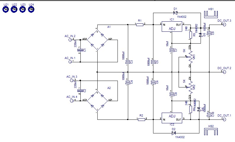
I thought during the last week on how I can use a cheap linear unregulated power supply with the cmoy I built and I did this circuit scheme. The right part come from tangentsoft.net cmoy instructions.


Do this two LM317 regulators will compensate for the lack of regulation from this DC wall power supply from mouser? (412-112055) This is a 12v output wall ps so to get regulated voltage, should I ajust the regulators to get 10v or 11v?
 
Thank you
 
Jun 13, 2011 at 8:38 AM Post #4 of 11
The LM317 drops about 3 volts to regulate the output.
This means for your 12 volt wall wort, you can only count
on getting about 9 volts. A better choice might be the
TLV1117 regulator. You can use it the same as the 317
but it only drops about 1.3 volts, less than half that of
the 317.
To fix your schematic, get rid on the lower 317 and connect
the top regulator to the negative side where the lower 317 was.
See the data sheet for more information.
 
Jun 13, 2011 at 9:12 AM Post #5 of 11
Here is a 12 volt fixed regulator for the TLV1117.
With your DC wall wort you don't have to use the
rectifier diodes. As long as you don't draw too much
current, you should be able to get 12 volts out of it.
If you do use the rectifier, you can pick a 12 volt AC
wall wort.


The part numbers are from Digi-Key.
The diodes are 1N4001.
 
Jun 13, 2011 at 9:19 AM Post #6 of 11
Thank you for the informations about the TLV1117. So If I understand, I can remove the lower 317 and connect each pin of the upper TLV1117 to te exact same place of the lower regulator circuit? This way one regulator can do both sides?
 
thanks for the schematic.
 
Jun 13, 2011 at 10:23 AM Post #7 of 11
If your interested in making the dual regulator version, the LM337 is the part you want for the negative rail. Im positive its a negative version of the LM317. You will also need some grounds in there. 
 
Whatever regulator your using, I would not test the lower limits of voltage overhead/voltage dropout. Try to keep at least 5V across the regulator no matter what the datasheet says, and 7-10V isn't too hard. I suppose at some point heat-sinking becomes a difficult task, but you can calculate how much heat the regulator will dissipate once you know the load current (Its not much for a standard Cmoy, or even Pimeta) and go from there. 
 
Jun 13, 2011 at 11:08 AM Post #8 of 11


Quote:
If your interested in making the dual regulator version, the LM337 is the part you want for the negative rail. Im positive its a negative version of the LM317. You will also need some grounds in there. 


There is a different LM317 regulator for the positive side and the negative side or it's the same part with a different pinout indicated une the datasheet? Can I use the virtual ground of the amp for the ground you mentioned?
 
Jun 13, 2011 at 12:29 PM Post #9 of 11
 
Quote:
There is a different LM317 regulator for the positive side and the negative side or it's the same part with a different pinout indicated une the datasheet? 


The negative version of the LM317 is a totally different part. 
 
If you build with a bipolar supply with dedicated +, -, and ground connections dont use a virtual ground circuit, they fight. 
 
The TPA LCBPS board is a good example, and all set to wire up :)
 
lcbps_schematic.jpg

 
Jun 13, 2011 at 1:49 PM Post #11 of 11
I found the part list that go with the schematic on twistedpearaudio, but I don't understand why there is three DC out. Is the DC out 2 a ground? If yes, will it completely replace the virtual ground and still work with a battery? I will probably end building both single and dual regulator version because the size of the first one seem to fit better for a cmoy, but the second looks like a nice challenge for me.
 

Users who are viewing this thread

Back
Top