Looking for a schematic for MF X-CAN V2

Oct 7, 2005 at 6:11 AM Post #2 of 29
AFAIK this schematic hasn't been floating around anywhere I've seen. I've seen several schematics to the XCans V1 but the designs are fairly different.

I do remember someone modding it though. I think the extent of the mods were capacitor replacements throughout.
 
Oct 8, 2005 at 7:55 PM Post #3 of 29
Yeh that was me.... some V2 stuff here. I'll see if I can get hold of a V2 schematic on Monday
smily_headphones1.gif
 
Oct 10, 2005 at 6:46 AM Post #5 of 29
Quote:

Originally Posted by PinkFloyd
Yeh that was me.... some V2 stuff here. I'll see if I can get hold of a V2 schematic on Monday
smily_headphones1.gif


Thanks!

I came across your site during a standard Google search. Seems like it's the only one like it. Looks like some good work.

If you can dig up a schematic, that would be really helpful, saving me the time to trace it.

Regards,

Rob
 
Oct 10, 2005 at 12:01 PM Post #6 of 29
Quote:

Originally Posted by weinstro
Thanks!

I came across your site during a standard Google search. Seems like it's the only one like it. Looks like some good work.


Lots more to come very shortly and this time pics taken with a "proper" camera
wink.gif
First up will be replacing the PSU caps with higher capacitance, changing the pot, swapping out the transistors for different types and lots more... stay tuned.

Quote:

Originally Posted by weinstro
If you can dig up a schematic, that would be really helpful, saving me the time to trace it.


The tech guy at MF is not in today but he'll be there tomorrow.... will ask him then
smily_headphones1.gif
 
Oct 11, 2005 at 12:08 AM Post #8 of 29
Quote:

Originally Posted by PinkFloyd
Lots more to come very shortly and this time pics taken with a "proper" camera
wink.gif
First up will be replacing the PSU caps with higher capacitance, changing the pot, swapping out the transistors for different types and lots more... stay tuned.


I think the first two are clear enough on your website. Can't see what the op-amp is, however.

Quote:

Originally Posted by PinkFloyd
The tech guy at MF is not in today but he'll be there tomorrow.... will ask him then
smily_headphones1.gif


OK. We'll apparently have to work around the copyright issues.

Anyway, do you recall the grounding scheme used on the 12 VAC input? In particular, is the 12 VAC center-tapped and balanced, or is the "neutral" somehow referenced to either mains neutral or ground?

Thanks,

Rob
 
Oct 12, 2005 at 1:31 PM Post #9 of 29
Quote:

Originally Posted by weinstro
I think the first two are clear enough on your website. Can't see what the op-amp is, however.


Opamp? what opamp? It doesn't have any.


Quote:

Originally Posted by weinstro
Anyway, do you recall the grounding scheme used on the 12 VAC input? In particular, is the 12 VAC center-tapped and balanced, or is the "neutral" somehow referenced to either mains neutral or ground?


It's simply a transformer with 12VAC secondaries connected to the AC input of the amp.
 
Oct 12, 2005 at 1:33 PM Post #10 of 29
Quote:

Originally Posted by rickcr42
BTW-do NOT post the schematics here or even the "my version xxxxx" schematics or they will be deleted by the forum moderators.

rickster


As if I would
confused.gif
 
Oct 12, 2005 at 2:00 PM Post #11 of 29
Quote:

As if I would


Was a general warning Mike just in case anyone got an idea to post it.
You know how this crew gets and by next week the clones would be offered as a project.NOT.
 
Oct 12, 2005 at 10:23 PM Post #12 of 29
Quote:

Originally Posted by weinstro
I'd like to do some modifications


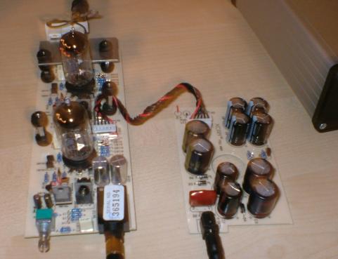
I just got hold of another X-Can V2 yesterday and have already started playing about with it
biggrin.gif
Just couldn't help myself as I had a few bits and bobs going to waste...... It's work in progress but so far this evening I've replaced the 6.3V 220uF non polar output caps with 6.3V 1000uF varieties bypassed with Evox polypropylene caps. Fitting higher capacitance output caps sure does make the bass go a lot deeper..... I'll probably get around to removing the output caps all together but for now 1000uF makes a big improvement.

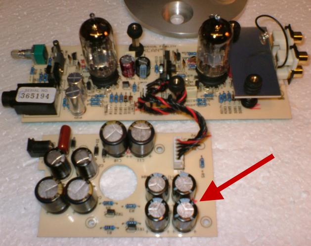
Also started fitting more capacitance onto the PSU board (upper board) this is the part of the X-can where fitting more capacitance reaps major improvements. There are 8 x 1000uF and 2 X 470uF as stock....... these can safely be replaced with much higher capacitance.... MF suggest replacing them all with 2200uF (if fitted in the X-Can enclosure) or the sky is the limit if fitting the boards into a larger enclosure. I only had a few caps to hand but have replaced 4 of the 1000uF with 1600uF and the two 470uF with 1000uF... the other 4 x 1000uF I'll replace with 2200uF once I get hold of some.

Swapped out some of the Jamicon caps for Nichicon fine gold and ELNA stargets in key areas and will also get around to bypassing them with film caps at some stage. Also fitted some rubber grommets to the stand offs to provide damping and will be rolling Mullards in once I've completed the rest of the mods this weekend.

The results so far? In a word......Outstanding. Bags more weight and delivery and oodles of warm luscious (yet very tight) bass, night and day over the stock V2 for sure. Changing the capacitors for another brand always reaps results in the V2 but increasing the capacitance brings about quite awesome improvements as does upping the output caps capacitance and fitting bypass caps..... I'm tempted (very tempted) to go absolutely mad with capacitance on the PSU board but that would mean either fitting an offboard cap bank or housing the V2 in a much larger enclosure and I'm not sure I'd want to do either as I like the aesthetics of the V2.

I'll upload everything to my website when the project is complete (probably next week sometime) I'm awaiting a replacement pot, caps, 0.1% resistors, some transistors and a few other bits and bobs.... in the meantime I'm just absolutely immersed in the music and am really really enjoying the music with this X-can!!

7.jpg

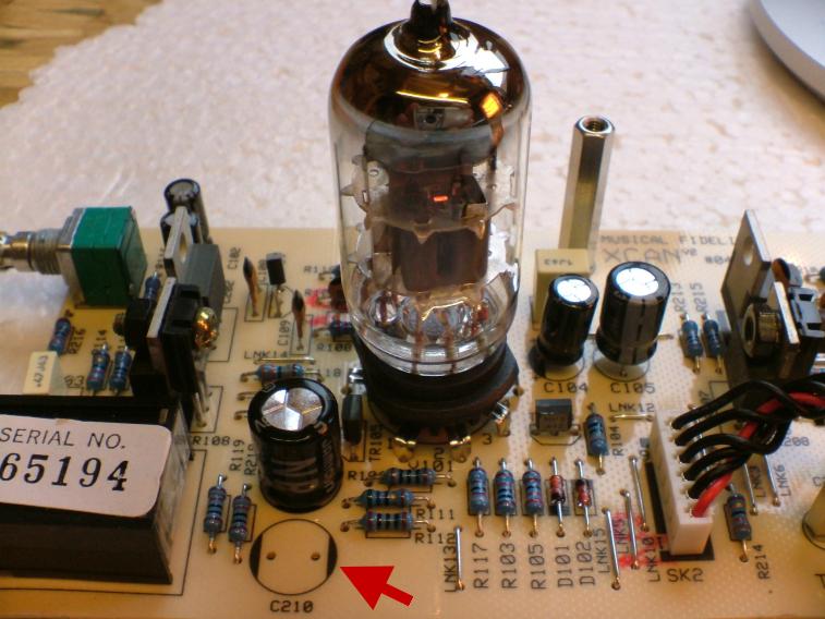
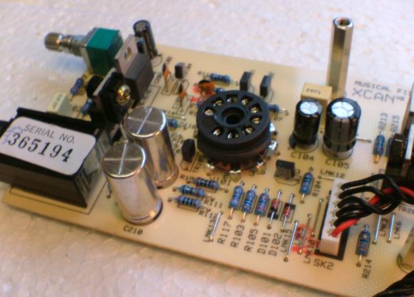
Removed the two 220uF non polar output caps

3.jpg

Replaced with 2 x 1000uF non polars

1.jpg

Bypassed the 1000uF non polars with polypropylene film caps on underside of board

5.jpg

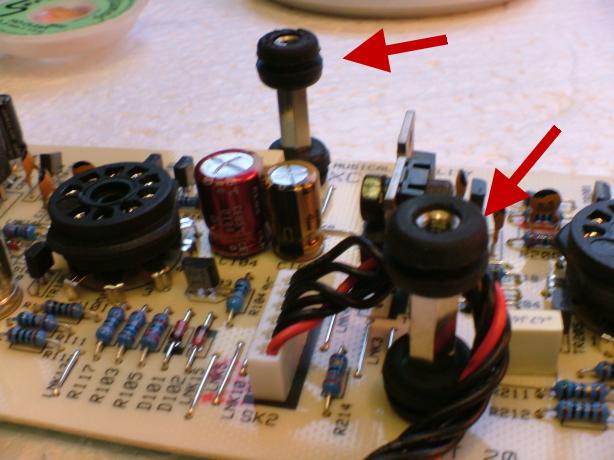
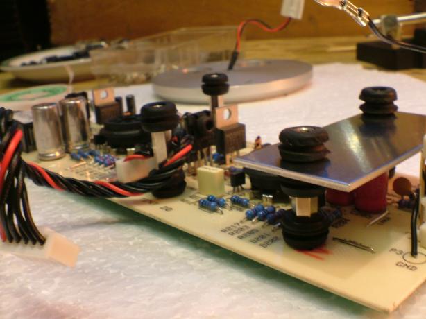
Fitted rubber dampening grommets to stand offs
6.jpg


8.jpg

These caps are still to be removed and replaced with 2200uF varieties

4.jpg

Enjoying the music!
 
Oct 13, 2005 at 8:31 PM Post #13 of 29
Still awaiting some parts so this evening was spent cutting out a couple of ventilation holes... well, not so much ventilation holes more like chimneys directly above the valves allowing the heat to escape through the holes...... will get around to fitting mesh as soon as some epoxy arrives
smily_headphones1.gif


hole1.jpg

Holes cut and primed ready for paint.

hole2.jpg

Close up of hole (looks a lot better in reality)

hole4.jpg


mesh.jpg

Dark Grey mesh ready to be cut and fixed into position.

I also "popped" the red LED out of the fascia ready to fit a 5mm diffused blue LED.

led1.jpg

Led popped out of hole

It may be of interest that the resistor directly above the red arrow is in series with the LED so this is the one to change if you're thinking about fitting a blue LED. The stock red LED uses a 330R resistor in this position and I guesstimate that swapping this for a 5K resistor would be ideal for a blue LED:

8.jpg


She's starting to take shape and should be finished on Saturday if the parts arrive tomorrow
smily_headphones1.gif
 
Oct 14, 2005 at 5:39 PM Post #15 of 29
Now you did it! I thought that once I finished my PPA I would be out of the DIY game for a while. My XCanV2 has been gathering dust since then. Now you got me thinking about it again. I did the general cap upgrade and psu clone. I really would like to change out that darn little plastic volume knob, but as discussed in a previous thread the pot shaft is too short and replacing it isn't an easy job. I really like the look of your mock-up with the valves sticking out. I don't have access to a drill press so that's not an option for me at the moment. Keep those ideas coming!
icon10.gif
 

Users who are viewing this thread

Back
Top