LMH6642 virtual ground not supplying enough current?

Jan 20, 2008 at 1:42 PM Thread Starter Post #1 of 10

mottl3y

New Head-Fier
Joined
Jan 20, 2008
Posts
5
Likes
0
I've been slowly progressing through my first ever headphone amp for the past week or so. I've followed Tangent's instructions for a CMoy, but I've used an LMH6642 to create the virtual ground.

I was having a problem with clipping. I don't have an O-scope, so I'm just assuming the static was due to clipping. If the source volume was way down, then the output was clean.

I read in heatmizer's post here that using some caps from V+/V- to ground helps for cases where the virtual ground can't source enough current. I stuck a pair of 220uF caps in, and the output sounds a lot better (still some quiet background hiss, but I'm hoping taking it off the breadboard will fix this). The caps fixing up a lack of current supply makes sense, but I have a couple of questions:

1. is there something wrong with my circuit in the first place if the LMH6642 was too weak for a CMoy (using a Burr Brown OPA2132)?

2. how do i know how big i want the caps? presumably a bigger cap means a bigger charge time - so the OPA2132 might not be getting its V+/V- as fast on first turn on which isnt really a problem, but it also means more electrons available for when they're needed.


This forum has been a great help in deciding on headphones, and with problem solving for my CMoy, thanks everyone!

m.
 
Jan 20, 2008 at 3:29 PM Post #2 of 10
I think more information is needed. What's your supply voltage? What phones do you use? Have you measured current draw and DC-offset? How do you decouple the opamps = did you use any capacitors at all before you added the 220uF's from rails to ground? LMH6642 is quite stable and easy to use, but it's still a fast opamp compared to OPA2134 and such. It needs decoupling - read the data sheet. It might have been the LMH oscillating if there was a clicking sound and insufficient power. How is LMH6642 implemented - unity gain? resistor in feedback loop? input resistor?

I've used LMH6642 a lot and never had problems with insufficient power, even at low supply and playing loud as hell. Hope it's not a LMH6624 you're using
tongue.gif
.
 
Jan 21, 2008 at 12:38 AM Post #3 of 10
sorry for not including enough detail

supply is 9V from a benchtop power supply, or from a 9V battery (when something doesn't fix the problem, I check that the problem is still there with the battery).

I'm testing with some old Sony headphones from a walkman or minidiscman. I really have no idea what their ratings are.

The only cap that was in the power section was across the power source (i.e. across the 0 and +9V inputs).

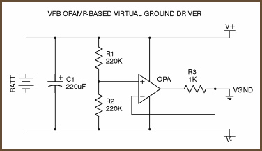
The LMH6642 is used instead of a BUF634 like so:
vfb-opa.png

credit to tangent for the pic, i hope he doesn't mind me hotlinking.

what do decoupling cap's do in a circuit? i assume the one across the power supply inputs is to send any non-DC signals to ground.
what should I be looking for in the datasheet for decoupling caps?

is the maximum current the 6642 can supply the "linear output current"? and is there a rating for the maximum voltage differential between the inputs and the ouput?

i tried removing the 1K resistor in the 6642's feedback loop, and tried it with and without the caps from the rails to virtual ground. the sound was worse than before, and i think the 6642 is fried, because now the ground is not centred. It's 7.8V from the negative rail and 0.8V from the positive.
 
Jan 21, 2008 at 7:05 AM Post #5 of 10
the circuit shown is simply wrong with any op amp, much less a 130 MHz one


for low (audio) frequency operation the 1K value of the series R must be a misprint - all of the R/L channel output current has to flow through it and a simple Ohms Law calc show it has to be less than 1/2 the lowest Ohm headphone load

for high frequency stability any R in series with the output shouldn't be inside the high frequency feedback loop - this drawing only shows one feedback path and the series R is inside

implementing one possible high frequency split feedback scheme requires a series feedback R to the Vgnd and a C between the inverting and ouput pins of the op amp - the feedback R senses the Vground on the far side of the output series R at low frequencies, at high frequencies the feedback C bypasses the sereis R and forms a low phase shift unity gain feedback path

other more certain high frequency stabilizing options exist but I would want to prototype and look at any circuit with a +200 Mhz scope before recommending this fast an op amp to any diyer
 
Jan 21, 2008 at 10:17 AM Post #6 of 10
Take a look at how it's done in Mini3 The Mini³ Portable Stereo Headphone Amplifier. This amp is stable. I would suggest you just implement the LMH6642 like in this amp. The combinantion OPA2132/LMH6642 might be a good one, since LMH6642 is a bit on the bright side of neutral.

I don't have an oscilloscope, but I never found LMH6642 problematic. No excessive current draw, hiss, clicks etc indicating oscillation. Contrary to jcx I find it easy to use. Just have those caps in close proximity to the power pins. I often solder the caps directly on the BrownDog adapter and use pins 1 and 8 as ground connection (they're not used in this opamp). The closer the caps are to the power pins the better, as I understand it.

I've used BrownDogged opamps with + 1 GHz BW on stripboard without obvious oscillation (AD8045, LMH6624). I've used other fast opamps like LMH6654, OPA690, LM6171, AD829 without obvious misbehaving. Some have been crankier like AD8099 and ADA4899-1. Like I said, I don't have an oscilloscope, so there might have been some low level oscillation or ringing.
 
Jan 22, 2008 at 5:34 AM Post #8 of 10
jcx:
the circuit shown is for a virtual ground. tangent's tutorial is reasonably in depth, so i dont think R5 would be a misprint. I don't really understand why you disagree with the circuit? why would R5 have to be lower than a headphone's impedance? i understand that all current through the headphones gets back to the ground through R5.

nelsonvandal:
i had a geez at the mini3, looks like an intelligent set up from my understanding (a rail splitter buffered by an op amp. but why do you need the 330R resistors on the inputs to the op amp?).

unfortunately the local electronics stores dont have the tle2426, and i don't think i can afford another delivery from Farnell. i will try sticking with my current set up (LMH6642 with caps from V+ and V- to ground). I tried putting in a couple of ceramic caps i found in an old stereo system (0.1uF i think, markings are F, 104, 25V, KCK), but the sound seems to clip at a lower volume than if i use the 220uF electrolytic caps i tried first. Is this because of the higher capacity of the electrolytics, or is it because of the material, or both?

any recommendations for improvements would be greatly appreciated. Im about to stick it into some proto-board, so probably wont change it once its in there
biggrin.gif
 
Jan 22, 2008 at 7:13 AM Post #9 of 10
Tangent undoubtley writes better programs, I design board level circuits with op amps for industrial/scientific measurement and control instrumentation

without more context the circuit you show implies use as a active gnd ala AMB's Mini^3, but apparently you are following Tangent's CMOY schematic - which puts critical parts on separate pages that makes evaulating the "Vgnd" operation difficult

adding the circuit shown together with the 2 220 uF caps AC splitting/shorting the battery to the Vgnd changes the operation considerably

the LMH6642 would be a suitable candidate for AMB's Mini^3 style active gnd circuit - which could be patched into the "CMOY" with the type of high frequency stabilzing circuit changes I outlined and the 2 220 uF caps removed

in Tangent's CMOY gnd circuit the LHM6642 capabilities are not only wasted but its excess gainbandwidth/speed are positively dangerous to the stability in this circuit application with the 220 uF caps in place

I would even reverse the application of the op amps - I would rather use the LMH as R/L channel amps and the OPA132/4 as a gnd amp with the 2 220 uF caps AC splitting the supply (although you would probably need ferrite beads on the outputs with the LMH for stability into the headphone cable capacitance)

the simplest advice is to use the much "safer", slower opa134 in all 3 positions - or reconnecting the gnd amp as a unity gain buffer of the supply splitting reistors midpoint and then connecting the output to the AC gnd with a ~100 Ohm R is closer to the tle2426 circuit
 
Jan 22, 2008 at 1:12 PM Post #10 of 10
I've observed that most people discussing the virtual ground idea doesn't fully uderstand it. Below is the simplest (and not very efficient due to op-amp out current efficiency) and correct virtual ground circuit - actually a copy of the TLE2426 internal schematic.

simplegndjr1.gif


However, some rules must be obeyed:
1) the op-amp is unity gain stable
2) There are no capacitors decoupling the rails to the ground. Only the rail-rail decoupling is allowed. You will build an oscillator instead of the amp then.
3) adding the capacitors in parallel to the voltage divider resistors is a common error - you kill the VGND bandwidth (speed and accuracy)
4) NFB resistor must be half of the divider resistors - it compensates any offset currents then.
5) VGND is one common ground, you don't need any VGND/ground channel division which actually cause corrupted negative feedback in the L/R channel NFB feedback due to different ground at the headphone out and the NFB.

OPA690 and similar will work, but it's possible to build better and more efficient ground channels.
 

Users who are viewing this thread

Back
Top