Impedance, Induction, Active ground, Three separate questions

Nov 28, 2009 at 1:33 AM Thread Starter Post #1 of 8

Reighlok

New Head-Fier
Joined
Sep 19, 2006
Posts
16
Likes
0
As always, I am sorry if these questions have been asked and answered a million times each.

1st question:
What causes some headphones to have a higher impedance than others? My AKG K240DF's are 600 ohms, and my Grado 325is's are 32 ohms. 600/32 =~20.
So, if the impedance is solely caused by the length of the wire in the voice coil, it stands to reason (maybe) that the AKG's voice coil contains 20 times the length of wire that the Grado's do. Maybe they do, I do not know. But twenty times the wire has to add weight, and I would think having a lighter voice coil is an advantage. It is hard to believe that the AKG has twenty time thinner wire.

2nd question:
Assuming that different headphones have different lengths of wire in the voice coil, and different diameters, then they would have different induction properties, right? Does the voice coil act as a induction coil? It would have to, right? Would not that impact the sound negatively? I thought that at a given width, the longer the wire the lower the induction coils frequency. Would not that make the AKGs worse than the Grados, assuming that the length of wire in the voice coil is twenty times longer? (BTW, I love my K240DFs).

3rd question:
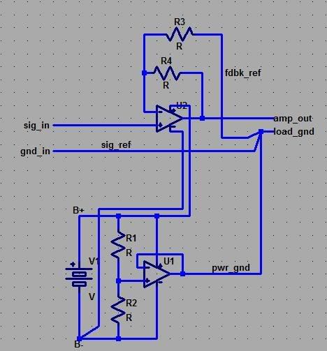
Completely different topic, sort of. Active grounds. I am planning on building a three channel beta 22 (from amb), and the third channel is a "active ground" that "actively sinks" the returns from the individual channels. My understanding of electronics is that components only see the potential difference between their input and output. So, having a normal ground seems... fine. Is the active ground acting as a quasi balanced return that effectively doubles the voltage the headphones see? That makes sense, not necessarily as a positive, but I at least get that. From what I read on amb's site though, that does not seem to be the case. So, what is the advantage of having an active ground? What is an active ground?

That is it. Thank you for any enlightenment you can bring me about these issues. Also, if these topics have been explained repeatedly either here or elsewhere, I would certainly appreciate any links you want to give me if you prefer that to explaining it again.

-Kyle
 
Nov 28, 2009 at 3:07 AM Post #2 of 8
With re. to question 1, higher impedance coils are usually achieved with thinner conductors or using aluminium conductors which don't conduct as well, I believe.
 
Nov 28, 2009 at 3:47 AM Post #3 of 8
I will give a quick explanation of impedance, as I think you may be interested and it will lead to your answers.

Impedance is analagous to resistance, except that is for an AC cir circuit ,whereas resistance is used for DC normally. What happens in things like capacitors and inductors is that in AC, there occurs a phase displacement between current and voltage, such that the change in current may lag behind the change in voltage at any given point in the circuit.

For a component, impedance is measured at a specific frequency, as it varies with frequency. Now, for a circuit working at only one frequency, we can make it totally analogous to resistance, as it is constant. But, audio works at a variably frequency, and thus what happens is that at higher frequencies, it may have a higher or lower resistance (part of what would cause rolloff for a particular driver setup). So, in finding at total impedance of components in series at any given frequency, we just add them. Resistors have impedances, but it is equal to just the resistance.

So, we have the resistnace of all the wires, plus any resistors that are there (think er4p or s). Then, there are the inductance values given by any coil of wire. You can change the impedance by coiling headphone cable. And the voice coil counts, too. But you have to realize that the impedance for an inductor also depends on inductance, which depends on things such as the number of turns and the cross sectional area. Thus, I could have many turns would very tightly, and one turn wound with a large area, and they could have the same inductance. So, there you have it. And yes, it may negatively impact the sound, but that is one of the reasons (aside not being massless) that drivers are not perfect.

-Nkk
 
Nov 28, 2009 at 4:09 AM Post #4 of 8
turns = transformer and same mass voice coil = same electo-mechanical-acoustic properties:

http://www.head-fi.org/forums/f4/wha...ml#post5944799


you could also try a (advanced) search for posts by me (jcx) with "3-channel" keyword for a slightly different from the head-fi "consensus" view by a practicing engineer, designer of scientiifc/industrial instrumentation who has to meet hard # on performance/measurement accuracy
 
Nov 28, 2009 at 5:39 AM Post #6 of 8
B0dhi: Al conductors? Hmm. I do not know how I feel about that.

Nkk:
I certainly was confusing impedance and resistance in my original post. I was just assuming that if I pulled out a multimeter and checked the resistance of my Grado and AKG headphones they would read 32 ohms and 600 ohms respectively, but I see now that need not be the case.

However, I thought (possibly mistakenly) that an induction coil only offered impedance above a certain freq. Or, maybe it drastically increased above a certain freq. So you could filter out high freq noise from an AC signal with one. Is that not the case? Are headphones doing that above a certain frequency?

jcx:
The more I read about active grounds the less I feel like I understand it. Really, I just want an intuitive understanding of the amp I am planning on building... So, when I let my brother listen to it, and he asks why there are three channels, I can say more than "it tests better that way".

Reading amb's posts about it changing the impedance the active channels see just confused me more. Changing impedance of the return path (and thus the whole path) is like changing the volume, right? So is it acting like a dynamic volume knob?

Clearly I do not understand.
 
Nov 28, 2009 at 6:08 AM Post #7 of 8
there are a few distinctions to watch:

"active gnd", "supply splitter"

when using a single supply like common wall warts or a 9V battery you need a gnd reference if you want to avoid big capacitors in the signal path, you need to create a 1/2 Vsupply reference for the signal and return for the driver current - but you can use the same mid supply "gnd" for both signal and output in a "star gnd" arrangement

"3-channel" is a added active output gnd channel to provide both R/L driver gnd - but not the signal gnd, a active buffer that has added noise, output impedance and distortion error in series with the signal gnd - so these errors appear in the output signal to the drivers - "3 channel" amps have separate signal reference and output gnds

"active gnd" can look a lot like "3 channel" if you don't pay attention to the signal gnd reference connection

a drawing of "active gnd" that is not "3-channel":
Quote:

Originally Posted by jcx /img/forum/go_quote.gif
3/4 channel "active gnd" schemes are not going to beat a good implementation of star gnd - any buffer op amp will introduce noise from its input stage and distortion from the nonlinear operation of its AB output stage and frequency dependant output impedance from the buffer internal feedback

properly layed out Cu trace and wiring to the output TRS connector as star gnd point doesn't introduce extra active device noise, can be orders of magnitude lower in Z at high audio frequencies and can avoid "gnd contamination" by virtue of separating the pwr_gnd branch of the star gnd so that load current doesn't flow in the sig_ref or fdbk_ref gnd branches

star.jpg


pwr_gnd could be (preferably) the center of a symmetric battery stack or dual ps instead of the "active gnd" battery splitter shown

but the star gnd scheme is still superior with the "active gnd" as imperfections in the supply splitter op amp oputput become common mode ps terms and the channel amplifier op amp's cm psrr is usually higher than its feedback loop gain and always at least equal to the internal loop gain


Nov 28, 2009 at 7:47 AM Post #8 of 8
Ok, so I typed a long explanation, and then my browser crashed. So I will do the following:

-point you to the wikipedia page, and a graph of the final outcome
-please feel free to PM me with questions. I am a physics major (and thus like to think I know what I am talking about), and would love to share the knowledge.

So, here is wikipeda: Electrical impedance - Wikipedia, the free encyclopedia

The part you need to know is:
inductor.jpg


Note that
L is inductance
Ip is max current (sin and cosine only go to 1 max, this a factor to make them bigger is needed)
w is frequenct
t is time
Z is impedance

I like to reduce the final equation down to

v(t)/I(t) = w*L / tan(w*t)

instead of having to change cos(wt) to sin(wt + pi/2) and still having two trig terms.

This shows that with an inductor, the current lags behind the voltage swing.

The graph is Z = i*w*L

i is the imaginary number, i = sqrt(-1).
Again, PM with any questions

-Nkk
 

Users who are viewing this thread

Back
Top