IC: DIY spdif switcher
Aug 14, 2009 at 12:24 PM Post #46 of 56
Quote:

Originally Posted by wackyterbacky /img/forum/go_quote.gif
Hello:

I know this question is not exactly on topic. In post 7 of this current thread:

http://www.head-fi.org/forums/f6/ic-...7/#post5258673

You show a Turtle Beach Micro with 44.1kHz output via Toslink.

I have one of these and have always read that it upsamples to 48kHz. I have not tried to test it.

Does it indeed output 44.1kHz?

Is it bitperfect?

Is this a function of some Linux driver or have you tested with a Windows PC.

Thanks.


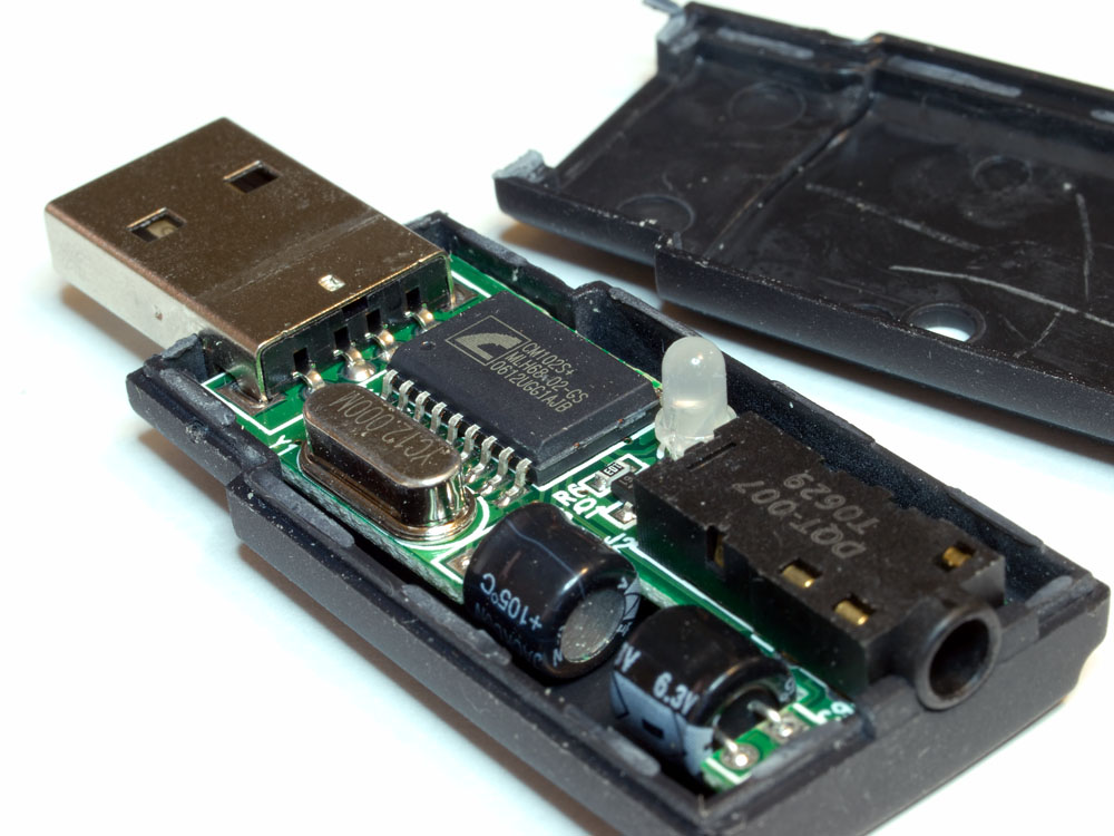
To the best of my knowledge, it is simply a PCM2707 feeding a toslink transmitter. You can find your answer in the PCM2707 datasheet. (I don't think it does upsampling.)
 
Aug 14, 2009 at 3:31 PM Post #47 of 56
Hi Brian:

I opened up my Turtle Beach and it has a CMedia CM102S+ The datasheet says:

USB 2.0 Full Speed Compatible and USB IF Certification
USB audio device class specification v1.0 Compatible
High performance 16-Bit Stereo, 48 / 44.1 KHz Sampling Rate for Audio Playback
Embedded X2 Modulation for Higher Audio Quality

I guess it does do 44.1 so I will try to set up a bit perfect test at some point. I will need coax spdif out and run it into my Juli@ Coax Input.

Thanks.
 
Aug 14, 2009 at 5:42 PM Post #48 of 56
re: turtle beach micro. it does not resample! my frequency display showed that
wink.gif


yes, it really honestly outputs at 44.1 when you play a redbook audio cd. or an mp3 created from it.

play a movie (down to stereo) and it shows 48.

all what you'd want and expect
wink.gif


its a good chip (the cmedia chip; always always has been, too!)
 
Aug 14, 2009 at 8:06 PM Post #50 of 56
Quote:

Originally Posted by TeraHz /img/forum/go_quote.gif
Here it is, ready to be cased. This slides right into one of the Hammond 1455C80x cases given that you cut the top for the LCD.
Next to my y2:
SPDF1-1.jpg


hey, you have a y2, also. I wrote a small bit of code to also control the features on *that*. you should do that, too. you can turn on/off that anti-clip and also turn on filter a/b/c. I think that's the 2 'features' that are natural to control, on the wolfson, while in hardware mode.

you need to put some OUTPUT wires in high-z mode or logical 0 or logical 1. to put the wire in high-z mode, you re-config the wire as INPUT. there is also some detail about pullup or pulldown R's based on how you wrote to the port while in OUTPUT mode or INPUT mode. have to check the arduino playground for more details.

but if you can spare some wires, I think you only need 2, to control those 2 features on the y2. and then you can display what you've done on the lcd and show the input port# (and name) but also any Y2 settings.

even more custom: if you wanted the y2 to be in 'noClip/filterA' on input 1 and maybe 'clip/filterC' on input 2, you could do that, too! one of the nice things about having control over the source code that is inside your own box
wink.gif
 
Aug 15, 2009 at 4:34 AM Post #51 of 56
that's a very interesting idea. I'll definitely look into it.

BTW here is how the whole thing fits in the case:

normal_spdifer-1.jpg


normal_spdifer-3.jpg


normal_spdifer-2.jpg


and now cased and working:
normal_spdifer-4.jpg


As you said, once you have an open source controller, there are so many fun things to do. I was thinking of displaying the current song playing from itunes, if anything is playing on the computer, and maybe the temperature outside in the lower right corner fetched from weather.com
smily_headphones1.gif


Anyways, It has been a very fun and educational project!
 
Aug 16, 2009 at 5:21 PM Post #52 of 56
Quote:

Originally Posted by TeraHz /img/forum/go_quote.gif

BTW here is how the whole thing fits in the case:


I see the lcd is not lying parallel to the box surface. how about some double side foam sticky tape between the ard module and the lcd? I would stick one side to the lcd and let the other side float (don't peel the layer off the bottom side). that will give some cushion but not really bond anything too permanent and it might be enough to make things 'level' inside.
 
Mar 16, 2010 at 11:58 PM Post #53 of 56
update:

I've just added HDMI switching to this project! its a sneaky little hack, but it works and works pretty well. costs $15 to get 3 ports (if found on sale) or under $30 at the normal price.

this is one that I got hold of and was able to 'hack':

Meritline.com - HDMI v1.3 + HDCP 3 Ports Mini Switch, intelligent Auto Switch and 3 pcs of 6 Feet HDMI v1.3 Male to Male Digital A/V Cable, 30 AWG Cable, Category 2 Certified, Support 1080P HD Resolution

today (16-mar) its on sale with this coupon code: MLCK195119031630AL1 but it often goes on sale.

the key to this hack is that the HDMI switch has an IR input via a cable. there are 2 ways to interface with this; via an indirect opto method (ir blaster and ir eye); or via an actual optocoupler chip. I've done the first one and it works, and I'll move onto the optocoupler when my chip order comes in.

this particular HDMI switch uses NEC style IR coding and it was simple to be able to 'sniff' the code and mimic it on the send side. adding one IR led (which, btw, can be taken directly out of the included handheld credit card style remote) and some code to SPDIFmaster, I was able to link spdif ports to hdmi ports.

the user can define any mapping of (spdif, hdmi), even repeated port numbers. when you select an input, it does a table (data structure) lookup and finds the corresponding spdif and hdmi port numbers to use. if the hdmi port number changed since the last button press, a new IR blast is sent out of the sender-led and this causes the HDMI switch to change to that new input (there's a discrete IR blast for each of the 3 ports, so there's no state that needs to be read or maintained).

you can locate the hdmi port box behind the cabinet or where ever the hdmi cables can reach. the point is that this box can be remote from the spdif switch box and they're just connected via a single cable. you don't need to uncase the hdmi switch or modify it or even allow for it inside your own chassis. it just acts like a 'pod' that has wires out of it but no user interface. the UI is coming from SPDIFmaster and its lcd display.

more details later when I have the optocoupler working.
 
Jun 15, 2011 at 12:30 AM Post #54 of 56

 
Quote:
Here it is, ready to be cased. This slides right into one of the Hammond 1455C80x cases given that you cut the top for the LCD.

3 spdif in, 1 spdif out, usb, IR, 2x16 lc:

Top view without LCD:
SPDF1-3.jpg


Top view with LCD:
SPDF1-2.jpg


Bottom view:
SPDF1-4.jpg


Next to my y2:
SPDF1-1.jpg


Hi TeraHz !!!!
 
Nice work whis arduino&ir remote.
[size=medium]You can upload more detail pics, I can't see all connect lines. [/size]
[size=medium]What value of adjustable resistance and what value of ir ditails?[/size]


Mar 26, 2012 at 1:54 AM Post #55 of 56
I'm coming very late to this party... Great work here from all participant's working the DIY selector versions/implementations.
 
When I originally converted my HT setup over to digital audio (and got rid of a 100 lbs and 100's of feet of analog video and audio cabling) my HT Receiver was not up to the task of taking in more than 2 digital sources.... so, what to do?  Spend 1) $1K-2K on a new receiver, or 2) get a digital audio input selector...
 
I chose option #2 and got a SPDIF / ADAT  4x1 Digital Audio Switcher doing up to 24/192 - 4 Coax/Toslink input into 1 Coax/toslink output from a Portland, OR company called INDAY  http://www.inday.com/da4x/da4x.htm
 
Its still my audio switch untility.  Works great, but its becoming very outdated.
 
I've been over and over Head-Fi, DIY Audio, etc, forums for different DIY DAC builds, cases and controls. 
 
An automatic (or user selected by IR remote) digital audio selection is a definite implementation/feature that I want in my DIY DAC build - likely replacing my inday unit - or at least, its current function.
 
But nowadays, the audio selection need is NOT limited to SPDIF (Coax/toslink.)  We've got several DAC kits available that do USB, I2S (I2C?:wink: direct DSD from modded SACD players, DSD over HDMI cable from Factory enabled SACD players, and soon to be dsd from PCs (ElecArt - etc,) AES/EBU, etc in 192/24 PCM, now up to 32/384 PCM... and so on.   I currently have 4 spdif sources... with 2+ more hi rate PCM likely in the near future with likely 2 DSD sources and a hi-rate USB coming soon as well.  I need my DAC to handle all of them.  I need it to auto detect/select, or be selectable with an IR mapped to my  "one to rule them all" remote - logitech 880 or similar high end HT theater programmable remote.
 
Ok - I'm rambling at this point....
 
So, the punchline is:
 
Linuxworks, TeraHZ, and other experts - can an HDMI or some other off the shelf or DIY switching unit take ALL COMERS I've identified above and route to the appropriate DAC inputs - SPDIF, Toslink, 32/384 PCM (?? spdif?), I2S, I2C, 2.8 DSD, 5.6 DSD etc. 
 
How could we do this type of switcher/selector?
 
I'm open to comments/suggestions, or just outright solutions.
 
Cheers,
 
Dave J  (aka JimiTheRottenKid / Jimmytrk)
 

Users who are viewing this thread

Back
Top