


StanD
Headphoneus Supremus
- Joined
- Oct 2, 2013
- Posts
- 9,002
- Likes
- 1,134
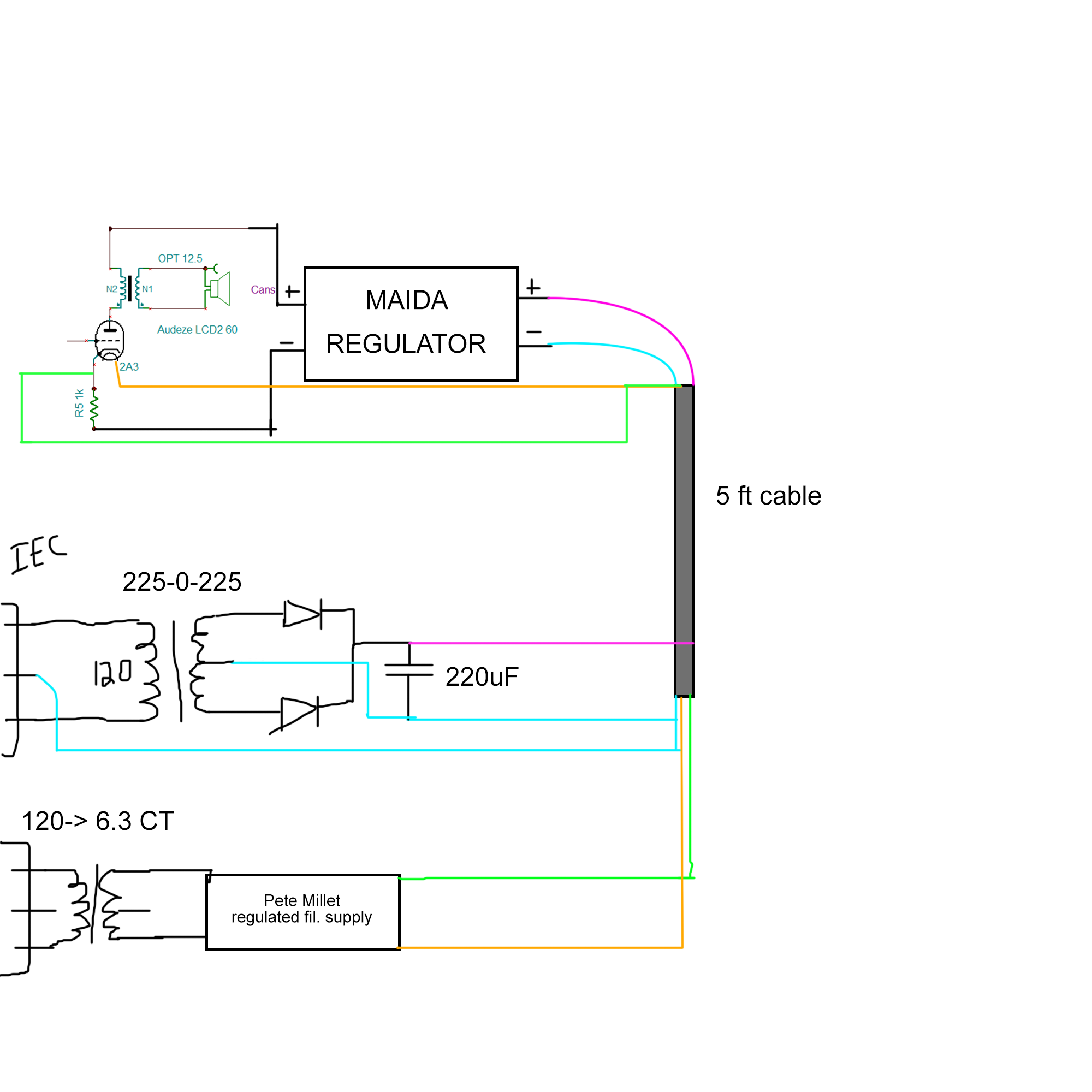
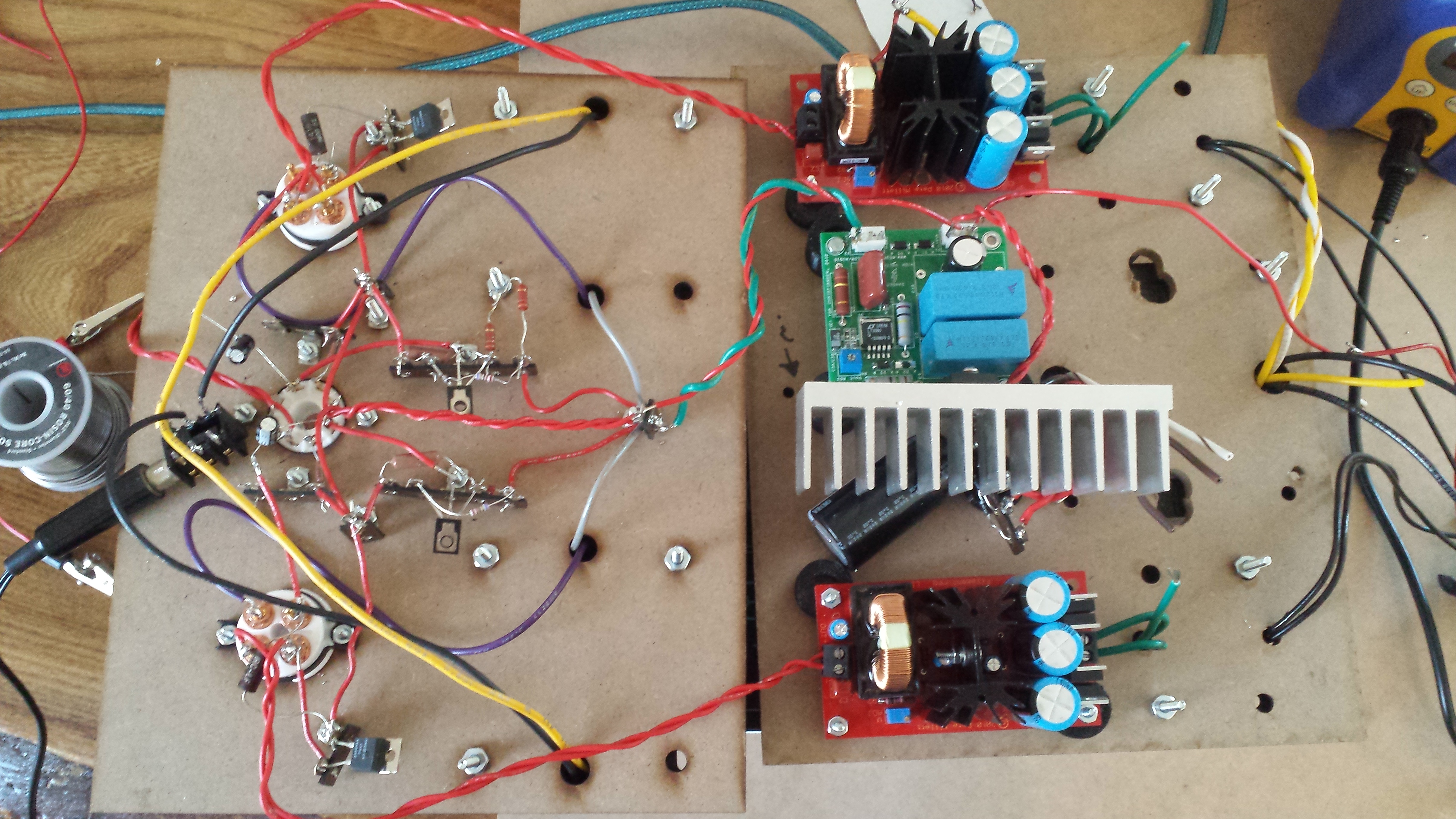
Your power transformer's secondary with the two diodes looks like there is no ground return. Usually one uses a bridge rectifier (4 diodes - full wave) and grounds the centertap of the secondary for +/- railes or uses one side of the bridge rectifier output to ground. Why is there a ground coming from the primary of the IEC transformer?
Is that the mains ground going to your chassis ground?
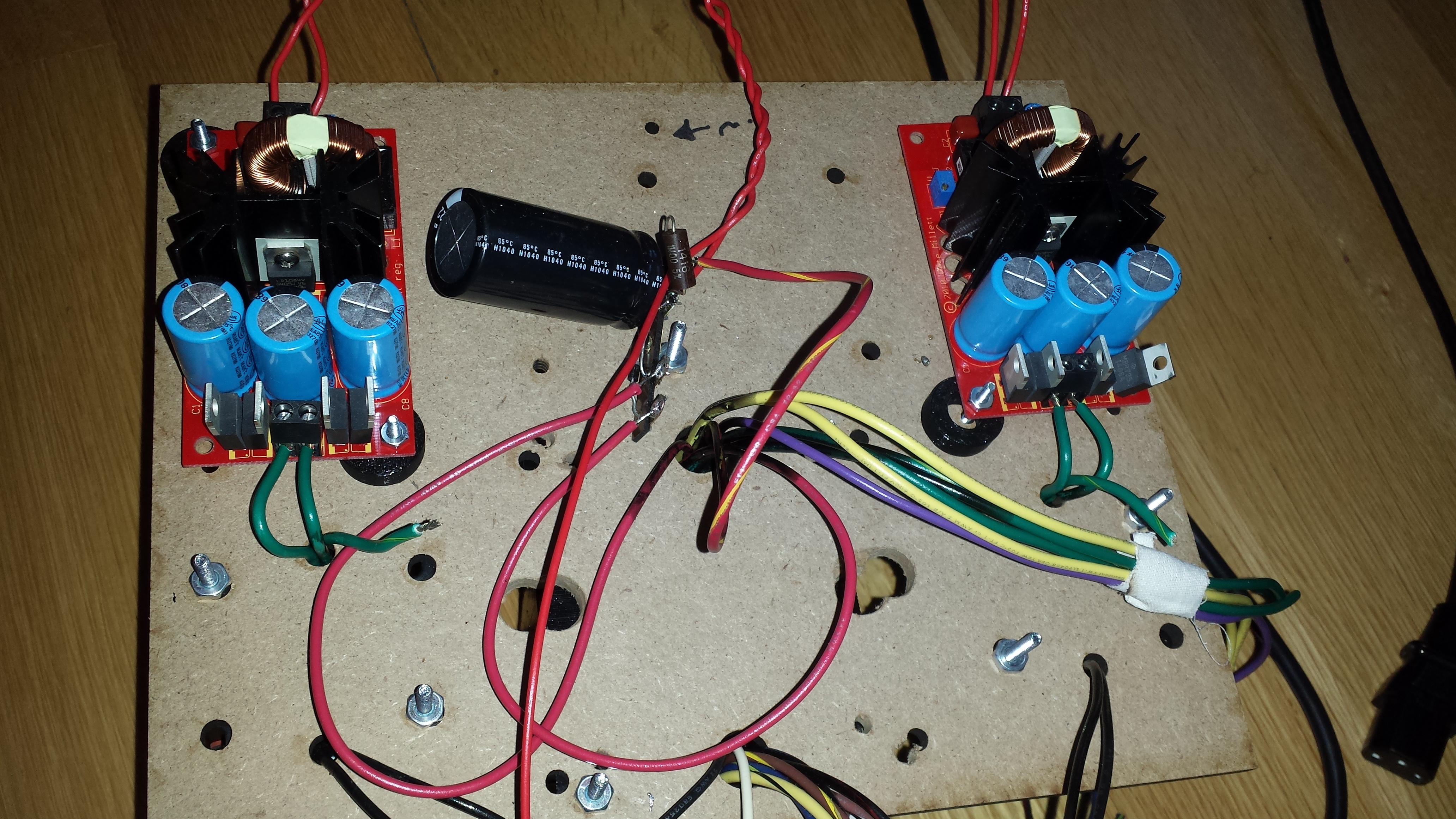
Does the Pete Millet Regulator have rectifier diodes or have they been omitted?


Is that the mains ground going to your chassis ground?
Does the Pete Millet Regulator have rectifier diodes or have they been omitted?
